background image

2

WARNING:

This equipment must be earthed.

To ensure safe operation, make sure that the optical 

cable is securely connected to an earthed CCU when 

in use.

The fact that the equipment operates satisfactorily 

does not imply that the power point is earthed or that 

the installation is completely safe. For your safety, if 

you are in any doubt about the effective earthing of the 

power point, please consult a qualified electrician.

WARNING:

•  To reduce the risk of fire or electric shock, do not 

expose this equipment to rain or moisture.

•  To reduce the risk of fire or electric shock, keep this 

equipment away from all liquids. Use and store only 

in locations which are not exposed to the risk of 

dripping or splashing liquids, and do not place any 

liquid containers on top of the equipment.

CAUTION:

Do not remove panel covers by unscrewing.

To reduce the risk of electric shock, do not remove the 

covers. No user serviceable parts inside.

Refer servicing to qualified service personnel.

CAUTION:

To reduce the risk of fire or electric shock and annoying 

interference, use the recommended accessories only.

CAUTION:

Excessive sound pressure from earphones and 

headphones can cause hearing loss.

CAUTION:

Invisible Laser radiation is emitted from the Optical 

fiber connector when this product is turned on.

Don’t look into directly into the Optical fiber connector 

of this product.

CAUTION:

Do not jar, swing, or shake the unit by its handle while 

another accessory is attached.

Due to the added weight, any strong jolt to the handle 

may damage the unit or result in personal injury.

CAUTION:

Do not lift the unit by its handle while the tripod is 

attached. When the tripod is attached, its weight will 

also affect the unit’s handle, possibly causing the 

handle to break and hurting the user. To carry the unit 

while the tripod is attached, take hold of the tripod.

CAUTION:

Do not leave the unit in direct contact with the skin for 

long periods of time when in use.

Low temperature burn injuries may be suffered if the 

high temperature parts of this unit are in direct contact 

with the skin for long periods of time.

When using the equipment for long periods of time, 

make use of the tripod.

CAUTION:

In order to maintain adequate ventilation, do not install 

or place this unit in a bookcase, built-in cabinet or any 

other confined space. To prevent risk of electric shock 

or fire hazard due to overheating, ensure that curtains 

and any other materials do not obstruct the ventilation.

CAUTION:

The optical cable shall remain readily operable.

To completely disconnect this equipment from the 

power supply, disconnect the optical cable from the 

equipment.

WARNING:

Always keep memory cards (optional accessory) or 

accessories (camera No. plate and D-sub connector 

cover) out of the reach of babies and small children.

 indicates safety information.

EEE Yönetmeliğine Uygundur.

EEE Complies with Directive of Turkey.

EU

Read this first!

To remove the battery

Back-up Battery (Lithium Battery)

•  For the removal of the battery for disposal at the end of its service life, please consult your dealer.

Содержание AK-HC3500AES

Страница 1: ...VQT5C18 DEUTSCH F r Erlauterungen in Deutsch konsultieren Sie bitte die mitgelieferte CD ROM Seite 4 FRAN IS Pour des explications en fran is veuillez vous reporter au CD ROM fourni page 4 ITALIANO Pe...

Страница 2: ...e another accessory is attached Due to the added weight any strong jolt to the handle may damage the unit or result in personal injury CAUTION Do not lift the unit by its handle while the tripod is at...

Страница 3: ...analog video signals Audio signal connecting cables If your apparatus supports AES EBU serial digital audio signals use cables designed for AES EBU Use shielded cables which provide quality performan...

Страница 4: ...INDEX pdf sur le CD ROM s ouvre la liste des manuels du mode d emploi s affiche Cliquer sur le nom du document correspondant au manuel consulter p p Adobe Reader est n cessaire pour lire les fichiers...

Страница 5: ...ol Contents Read this first 2 Overview 5 Accessories 6 Features 6 Precautions for use 7 Controls and their functions 8 Mounting the lens 14 Adjusting the lens flange back 15 Performing the viewfinder...

Страница 6: ...can be reduced since the fan mode can be switched according to the situation in which the camera system is being applied As a result the heat dissipation design has also been optimized Fuller compleme...

Страница 7: ...to clean the camera if it is dirty In case the dirt is hard to remove use mild detergent and wipe gently Use caution when operating the camera in the vicinity of spot lights or bright lights as well...

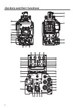
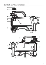
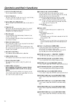
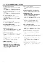
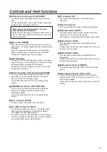
Страница 8: ...8 Controls and their functions...

Страница 9: ...9 Controls and their functions...

Страница 10: ...m an external power supply input connector and turn the power OFF CCU When connecting this unit to the CCU supply power from the CCU and turn the power ON EXT When connecting the external DC power sup...

Страница 11: ...are output from this connector Genlock sync input PROMPT output connector BNC PROMPT GL When the GL PROMPT selector switch is set to GL the reference signal tri level SYNC or B B which is used to gen...

Страница 12: ...d and the filter local LED lights the optical filter can be adjusted manually When it is pressed again the optical filter can be controlled by the ROP Filter local LED LOCAL While this LED is lit the...

Страница 13: ...tic black balance adjustments ABB It is not effective when the CCU is connected to the camera Lens connector LENS The lens cable is connected to this connector Front MIC1 connector MIC1 A microphone o...

Страница 14: ...ce Lens clamp lever 4 Insert the cable into the cable clamp and connect it to the lens connector Lens connector For details on handling the lens refer to the instructions that accompany the lens Depen...

Страница 15: ...s to manual and open the iris 3 Set the lighting in such a way that the appropriate video output level is obtained at a distance of about 3 metres from the flange back adjustment chart If the video le...

Страница 16: ...nob 3 Tighten the stopper screw securely Stopper screw 4 Connect the plug to the VF connector When connecting the plug to the VF connector ensure that it is fully and securely inserted Note Detaching...

Страница 17: ...ew Stopper screw Forward or backward position adjustment 1 Rotate the viewfinder forward backward position fixing lever towards the outside to release it from the locked position Viewfinder forward ba...

Страница 18: ...can be mounted on the viewfinder 1 Open the microphone holder Microphone holder 2 Mount the microphone and tighten up the clamp screw Clamp screw 3 Connect the microphone cable to the front MIC1 conne...

Страница 19: ...heck that the camera is secured properly Detaching the camera from the tripod adaptor While pushing the red lever move the black lever in the direction of the arrow and slide the camera toward the bac...

Страница 20: ...e to be controlled The basic system configuration includes the lens Studio Handy Camera viewfinder camera control unit CCU and remote operation panel ROP System block diagram Microphone Kit AJ MC700 2...

Страница 21: ...MSU can operate up to 12 units either separately or simultaneously by remote control It can be operated together with the ROP 2 type Electronic HD Viewfinder 2 VF AJ HVF21KG This is the viewfinder for...

Страница 22: ...i cable Before proceeding with the connections set the CCU power switch to the OFF position Connect the optical fibre multi cable to the Studio Handy Camera and CCU Connect the ROP cable to the CCU an...

Страница 23: ...tudio Handy Camera 12 AK HC3500AE ES Camera Control Unit 11 AK HCU355AE ES Camera Control Unit 12 AK HCU355AE ES Remote Operation Panel 11 AK HRP935AE Remote Operation Panel 12 AK HRP935AE Optical fib...

Страница 24: ...the automatic adjustment memory selected for the white balance A The WHITE BAL switch is set to A B The WHITE BAL switch is set to B P The WHITE BAL switch is set to PRST Gain display This indicates t...

Страница 25: ...a s auto functions Set Status AUTO to ON at VF Display2 under Operation When AWB is executed 1 AWB LOW LIGHT Auto white balance cannot be executed because the light quantity is insufficient Set the li...

Страница 26: ...FF Center Mark SEL 3 Line Width 3 Marker Level 100 2 When the JOG dial is pressed the setting of the item indicated by the arrow flashes VF Setting1 Side Modu SW OFF Side Modu LVL 15 Zone Mark 4 3 Saf...

Страница 27: ...ET1 ID ABCDE RET2 ID IJKLM RET3 ID QRSTU RET4 ID YZ012 Gain SW LOW 0dB Gain SW MID 6dB Gain SW HIGH 12dB ID Character ABCDEFGHIJ RET C Select 1 RET A RET B RET C 2 Turn the JOG dial to change the sett...

Страница 28: ...Focus for setting the focus value display to ON or OFF Extender for setting the lens extender display to ON or OFF MONI OUT for setting the monitor output selection display to ON or OFF Filter for set...

Страница 29: ...Black Gamma for displaying the status when the black gamma is ON VF FAN Speed for controlling the fan speed of the CRT viewfinder Peak Slice for setting the peak slice function Peak FREQ for selectin...

Страница 30: ...e H SAW H PARA R G B for adjusting the H PARA V SAW R G B for adjusting the V SAW V PARA R G B for adjusting the V PARA Gamma adjustments Gamma Gamma for setting the gamma to ON or OFF Gamma Mode SEL...

Страница 31: ...e for selecting the detail source DTL_Clip for adjusting the clip on the detail side DTL_Clip for adjusting the clip on the detail side Detail adjustments2 Detail2 DTL_Knee for adjusting the knee comp...

Страница 32: ...the reference file on the auto setup M PED Target for setting the master pedestal on the auto setup ASU Execute for executing the auto setup Tally guard setting Tally Guard Tally Guard for setting the...

Страница 33: ...splaying the FPGA version CAM for displaying the FPGA version AVIO for displaying the FPGA version AUX for displaying the FPGA version CAMSYS for displaying the FPGA version OPTION for displaying the...

Страница 34: ...8M 13M 6 8M D1 Offset Gain 0 to 5 0 D1 Crisp 0 to 63 0 VBS Peak FREQ 2 0M 2 3M 2 7M 3 4M 4 5M 6 8M 13M 6 8M VBS Offset Gain 0 to 5 0 VBS Crisp 0 to 63 0 Cursor Cursor OFF ON OFF Cursor Memory ADJ 1 2...

Страница 35: ...TABLE BOX BOX Rear ROP VR CAM CCU CAM LED Gamma Off OFF ON OFF Shutter OFF ON OFF Extender OFF ON OFF MONI OUT OFF ON OFF FAN Off OFF ON OFF Master Gain OFF ON OFF Black Gamma OFF ON OFF 7 VF VF FAN S...

Страница 36: ...0 V SAW R G B 100 to 100 0 V PARA R G B 100 to 100 0 Gamma Gamma OFF ON ON Gamma Mode SEL HD FILMLIKE1 to FILMLIKE3 HD Gamma M When Gamma Mode SEL is HD 0 600 to 0 300 When Cinema Gammma SW is ON 0 75...

Страница 37: ...es OFF A B A G Satu 128 to 127 0 G Phase 128 to 127 0 G_Cy Satu 128 to 127 0 G_Cy Phase 128 to 127 0 Cy Satu 128 to 127 0 Cy Phase 128 to 127 0 Cy_B Satu 128 to 127 0 Cy_B Phase 128 to 127 0 B Satu 12...

Страница 38: ...15 0 DTL_Knee 0 to 15 0 Knee DTL 0 to 39 5 Skin Tone1 Skin Tone DTL OFF ON OFF Skin Tone Get EXECUTE YES Skin Tone Get CANCEL YES MEM Select A B A Cursor OFF ON OFF H Cursor 1 to 1920 960 V Cursor 1 t...

Страница 39: ...t EXT Lens magnification display File Filename Gain R 100 to 100 0 Gain G 100 to 100 0 Gain B 100 to 100 0 Flare R 100 to 100 0 Flare G 100 to 100 0 Flare B 100 to 100 0 W H SAW R G B 100 to 100 0 W H...

Страница 40: ...FF 60 100 125 250 500 1000 1500 2000 50 i 48 50 60 96 100 120 250 500 23 98p 25p When SHUTTER is ON SYNCHRO is ON 51 5 Hz to 6250 Hz 50 i 24 7 Hz to 3000 Hz 23 98p 25 7 Hz to 3125 Hz 25p When SHUTTER...

Страница 41: ...2000 23 98p 25p 48 50 60 96 100 120 250 500 125 Position4 50 i 60 100 125 250 500 1000 1500 2000 23 98p 25p 48 50 60 96 100 120 250 500 250 Position5 50 i 60 100 125 250 500 1000 1500 2000 23 98p 25p...

Страница 42: ...f the file to be loaded or stored here Setting range 1 to 8 The files on the SD memory card have filenames which range from 350ACM01 DAT for File No 1 to 350ACM08 DAT for File No 8 The SD memory card...

Страница 43: ...gnal 1 FRONT_MIC_GND 2 FRONT_MIC H 3 FRONT_MIC C VF HR12 14RA 20SC Hirose Pin Signal 1 VF 12V 2 VF 12V 3 UNREG_GND 4 VF PBOUT_GND 5 VF PBOUT_GND 6 VF YOUT 7 VF YOUT_GND 8 VF_CLK 9 VF_WR 10 VF_DATA 11...

Страница 44: ...44 External dimension drawings Unit mm 360 260 105 135...

Страница 45: ...Hz interlace 12 Output formats 1080 59 94i 1080 50i 1080 29 97PsF 1080 25PsF 1080 23 98PsF over59 94i Input output signals 1 MIC input 60 dBu to 4 dBu XLR 3 pin female 2 Gain selected by camera menu...

Страница 46: ...MIC gain MIC1 selection 15 Optical filter setting REM LOCAL selection and LOCAL setting 16 Back light SW rear panel ON OFF When the CCU is connected the selection functions for 6 to 10 are not effect...

Страница 47: ...47 Memo...

Страница 48: ...y your waste disposal service or the point of sale where you purchased the items Penalties may be applicable for incorrect disposal of this waste in accordance with national legislation For business u...

Отзывы: