


11
RET-A selector switch [RET A]
This switch is used to select the return images to be
switched by RET-A.
The return images which have been set on the ROP
menu are allocated to this switch.
RET-B selector switch [RET B]
This switch is used to select the return images to be
switched by RET-B.
The return images which have been set on the ROP
menu are allocated to this switch.
CALL LED
This lights up green when the CALL switch is pressed
from the ROP, MSU or CCU.
CALL switch [CALL]
This lights the CALL LED on the ROP or MSU and
sounds the buzzer (when ON has been selected as the
buzzer setting).
OPT LED
This indicates the camera’s optical signal reception
status. It normally lights up green. When any problem has
occurred, it lights up red.
When a problem has occurred, clean the optical fibre
connector.
If the problem is not cleared up, immediately turn off the
power, and contact your dealer.
Back tally LED selector switch
This is used to set the back tally LED to ON or OFF.
Back tally LED
This lights when the tally signal is supplied.
This lights up red when the R tally signal is supplied,
green when the G tally signal is supplied, and red when
both the R and G tally signals are supplied.
RET switching control connector [RET CONT]
The cable of the RET switching box (optional accessory)
is connected here for controlling the ON/OFF of RET1, 2,
3 and INCOM1, 2 MIC.
External I/O [EXT I/O]
This signal interface connector is designed to support
future interfacing with external devices.
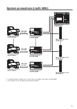
Camera HD-SDI output1 connector (BNC)
[HD-SDI1]
The camera HD-SDI images are output from this
connector.
Camera HD-SDI output2 connector (BNC)
[HD-SDI2]
Camera images, VF images or RET images can be
selected on the camera menu to output HD-SDI signals
from this connector.
Optional video connector (BNC) [AUX]
When the CCU has a Prompt2 input, the Prompt2 images
input from the CCU are output from this connector.
Genlock sync input/PROMPT output connector
(BNC) [PROMPT/GL]
When the GL/PROMPT selector switch is set to GL,
the reference signal (tri-level SYNC or B.B.) which is
used to genlock the camera is input to this connector;
Genlock sync signals are input to this connector when
the CCU is not connected. When it is set to Prompt, the
Prompt images input from the CCU are output from this
connector.
GL/PROMPT selector switch
This is used to select the genlock input or the input/output
(genlock input and PROMPT output) signals of the
PROMPT output connector.
Remote connector [REMOTE]
This connector is used for remote control.
External power supply input connector [DC IN]
The input of the external DC power supply is connected
to this connector. (DC 10.8 V to 17 V)
<Notes>
• Inrush current occurs when the power of this unit is
turned on. Insufficient power supply capacity at power
on may cause a failure.
It is recommended to use an external DC power supply
with a capacity that is at least double the total power
consumption of this unit and components (viewfinder,
etc.) whose power is turned on when the power of
this unit is turned on. For the DC cable, use a 2-core
shielded cable with a core cross section equivalent to or
larger than AGW18 (nominal cross section 0.824 mm
2
).
• When using the external DC power supply, be sure to
turn ON the camera power switch of the external DC
power supply and then turn ON the camera power
switch of this unit. If you turn on the power in reverse
sequence, the output voltage of the external DC power
supply rises slowly so this unit may malfunction.
• Check the pin assignment of the DC output terminal on
the external DC power supply and the pin assignment
of the DC IN terminal on this unit, and connect the
terminals with the correct polarity. (page 43)
Incorrect connection of the 12 V power supply terminal
to the GND terminal may cause a fire or failure.
MIC1 selector switch [LINE/FRONT MIC/MIC]
This is used to switch the input signal to LINE, front MIC
or rear MIC.
Controls and their functions
Содержание AK-HC3500AES
Страница 8: ...8 Controls and their functions...
Страница 9: ...9 Controls and their functions...
Страница 44: ...44 External dimension drawings Unit mm 360 260 105 135...
Страница 47: ...47 Memo...


