background image

Communication  

GTW/EN 

CT/C40 


PACiS Gateway 


Page 47/64 


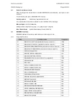
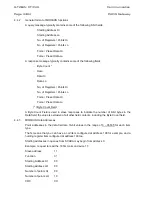
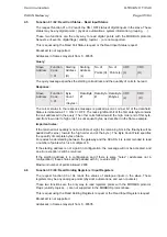
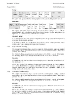
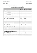
OBJECT 

REQUEST


(slave must parse) 

RESPONSE


(master must parse) 

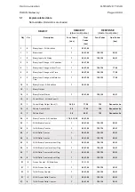
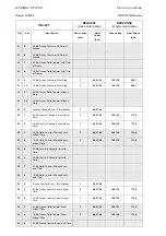
Obj Var 

Description 

Func 

Codes

(dec) 

Qual 

Codes 

(hex) 

Func Codes 

Qual Codes 

(hex) 

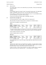
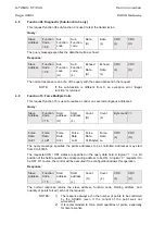
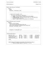
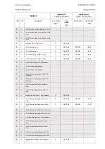
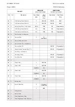
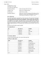
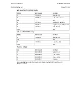
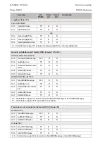
90 

Application Identifier 


100 

Short Floating Point 


100 

Long Floating Point 


100 

Extended Floating Point 


101 

Small Packed Binary-Coded Decimal 


101 

Medium Packed Binary-Coded 
Decimal 


101 

Large Packed Binary-Coded Decimal 


No Object (Cold Restart) 


No Object (Warm Restart) 


No Object (Delay Measurement 


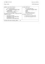
(1) Commands must be selected/executed on one point 

(2) may be possible 


Содержание GTW/EN T/C40

Страница 1: ...PACiS GTW Gateway GTW EN T C40 Version 4 5 Technical Guide ...

Страница 2: ......

Страница 3: ... IT C40 Hardware Description GTW EN HW C40 Connection GTW EN CO C40 Installation GTW EN IN C40 Human Machine Interface GTW EN HI C40 Communications GTW EN CT C40 Commissioning GTW EN CM C40 Record Sheet GTW EN RS C40 Maintenance GTW EN MF C40 Problem Analysis GTW EN PR C40 Functional Description GTW EN FT C40 Logic Diagrams GTW EN LG C40 Glossary GTW EN LX C40 ...

Страница 4: ...GTW EN T C40 Technical Guide Page 2 2 PACiS GTW gateway BLANK PAGE ...

Страница 5: ...Safety Handling GTW EN SA C40 PACiS GTW gateway SAFETY HANDLING ...

Страница 6: ......

Страница 7: ...SAFETY 4 2 1 Health and Safety 4 2 2 Explanation of symbols and labels 4 2 3 Installing Commissioning and Servicing 4 2 4 Decommissioning and Disposal 4 3 GUARANTIES 5 4 COPYRIGHTS TRADEMARKS 6 4 1 Copyrights 6 4 2 Trademarks 6 5 WARNINGS REGARDING USE OF SCHNEIDER ELECTRIC PRODUCTS 7 ...

Страница 8: ...GTW EN SA C40 Safety Handling Page 2 8 PACiS GTW gateway BLANK PAGE ...

Страница 9: ...CiS GTW gateway Page 3 8 1 INTRODUCTION The present document is a PACiS GTW gateway chapter of the documentation binders It describes the safety handling packing and unpacking procedures applicable to PACiS GTW gateway software tools ...

Страница 10: ... of symbols and labels may be used on the equipment or in the product documentation is given below 2 3 Installing Commissioning and Servicing Equipment operating conditions The equipment PC and communication network supporting PACiS GTW gateway should be operated within the specified electrical and environmental limits Fibre optic communication Optical LED transceivers used in Switch boards are cl...

Страница 11: ...t Schneider Electric if errors are suspected In no event shall Schneider Electric be liable for any damages arising out of or related to this document or the information contained in it Expect as specified herein Schneider Electric makes no guaranties express or implied and specifically disclaims and guaranties of merchantability or fitness for a particular purpose Customer s rights to recover dam...

Страница 12: ... or mechanical including photocopying recording storing in an information retrieval system or translating in whole or in part without the prior written consent of Schneider Electric 4 2 Trademarks PACiS PACiS SCE PACiS ES PACiS SMT PACiS PS PACiS GTW PACiS OI are trademarks of Schneider Electric Product and company names mentioned herein are trademarks or trade names of their respective companies ...

Страница 13: ...tware unanticipated uses or misuses or errors from the user or applications designer adverse factors such as these are collectively termed System failures Any application where a system failure would create a risk of harm to property or persons including the risk of bodily injuries and death should not be reliant solely upon one form of electronic system due to the risk of system failure to avoid ...

Страница 14: ...GTW EN SA C40 Safety Handling Page 8 8 PACiS GTW gateway BLANK PAGE ...

Страница 15: ...Technical Data GTW EN TD C40 PACiS GTW gateway TECHNICAL DATA ...

Страница 16: ......

Страница 17: ...nmental 6 2 10 Mechanical 6 2 11 Safety 6 2 12 EMC TESTS 7 2 13 Wiring 8 3 FANLESS EMBEDDED BOX PC CHARACTERISTICS 9 3 1 Operating System 9 3 2 Configuration 9 3 3 Communication ports with SCADA 9 3 4 Mechanical 9 3 5 Power Supply 9 3 6 Environment Specifications 9 3 7 Wiring 10 3 7 1 Serial connection 10 3 7 2 Ethernet connection 10 4 SOFTWARE GATEWAY CHARACTERISTICS 11 4 1 Number of Data Points ...

Страница 18: ... Technical Data Page 2 14 PACiS GTW gateway 6 LIMITS AND PERFORMANCES 13 6 1 Exchanging message with SCADA 13 6 2 SBUS acquisition 13 6 3 Time Performance 13 7 SYSTEM DEPENDABILITY 14 7 1 MTBF 14 7 2 Availability 14 ...

Страница 19: ... industrial PC described thereafter For more information about hardware description see chapter HW For more information about connection diagrams see chapter CO 1 1 General features A PACiS GTW gateway can manage up to 4 protocols and up to 8 channels Different kinds of links are available list is not limited to the ones given PSTN MODEM external device Radio link through MODEM Ethernet Features L...

Страница 20: ... serial ports by protocol 2 main redundant Thus 8 ports maximum on one gateway 2 cards with 4 ports Number of communication port settable by PACiS SCE 8 Baud rate bits s from 300 to 19200 settable by PACiS SCE In the industrial PC configuration described below the motherboard has two serial communication ports You can use them for one communication with SCADA plus a redundant port or two communica...

Страница 21: ...requency 100Hz or 120Hz 12 x Vn AC ripple frequency 200Hz for information 2 7 AC auxiliary supply TEST INTERNATIONAL STANDARD Harmonised Supply variations IEC 60255 6 Vn 20 Dips Short interruptions IEC 61000 4 11 2ms to 20ms 50ms to 1s Frequency fluctuations IEC 60255 6 From 44 to 55Hz Harmonics Immunity IEC 61000 4 7 5 over the range 2nd to 17th 2 8 Insulation TEST INTERNATIONAL STANDARD Harmonis...

Страница 22: ...cles of 24h 2 10 Mechanical TEST INTERNATIONAL STANDARD Harmonised Vibration response energised IEC 60255 21 1 Class 1 Vibration endurance non energised IEC 60255 21 1 Class 1 Shock response energised IEC 60255 21 2 Class 1 Bump non energised IEC 60255 21 2 Class 1 10g 16ms 2000 axis Seismic energised IEC 60255 21 3 Class 1 Drop no packaging IEC 60068 2 31 Test Ec 2 drops from 50mm corner drop and...

Страница 23: ...mmunity IEC 61000 4 5 Level 3 on power supply 2KV CM 1KV DM Level 3 on communication 2KV CM Conducted RFI Immunity IEC 61000 4 6 10Vrms 150KHz to 80MHz Power Frequency Magnetic Field Immunity IEC 61000 4 8 30A m continuous Damped Oscillatory Magnetic Field Immunity IEC 61000 4 10 10A m High Frequency Disturbance IEC 61000 4 12 Class III on power supply 2 5KV CM 1KV DM 1MHz 400 bursts s 100KHz 50 b...

Страница 24: ...iS GTW gateway is full compatible with standard RS232C A SCADA communication can be establish on one serial port One more serial port is needed for redundancy A Null Modem cable can be connected to a SCADA simulator or a Network Analyser For more information about the connection see the chapter CO ...

Страница 25: ...edundant Number of Ethernet ports 2 x 10 100 Mbps RJ45 connector Baud rate bits s from 300 to 19200 settable by PACiS SCE In the ADVANTECH PC configuration described below the PC has two serial communication ports and 2 Ethernet communication ports You can use them for one communication with SCADA plus a redundant port or two communications with SCADA 3 4 Mechanical Construction Aluminum housing M...

Страница 26: ...able can be connected to a SCADA simulator or a Network Analyser For more information about the connection see the chapter CO 3 7 2 Ethernet connection The connection with the PACiS GTW gateway is full compatible with standard 10 100 Mbps RJ45 A SCADA communication can be establish on one ethernet port One more ethernet port is needed for redundancy A cross ethernet cable can be connected to a SCA...

Страница 27: ... 14 4 SOFTWARE GATEWAY CHARACTERISTICS 4 1 Number of Data Points Refer to 1 1 4 2 Response time Time to receive a response after sending a request 100ms 4 3 SBUS Avalanche The linked list that manage events can memorise 15 000 events by protocol processes ...

Страница 28: ...filter 2070368A08 GI74 Supply 110VDC and filter 2070368A09 GI74 Supply 220VAC and filter 9565913 Serial board BCOM8 from ASE INDUSTRIAL PC base version Rack Schneider Electric GI74 CPU TEKNOR PCI 946 P3 700 Memory 128 Mo PC100 SDRAM FDP PICMG PCI 7S version G1 Flash disk IDE 16 Mo Cable Flash disk adapter Floppy driver 3 5 Cable Floppy Board reprise unpopulated Cable LED Cables COM1 COM2 TABLEAU 2...

Страница 29: ...synchronisation pre and post transmission times 6 2 SBUS acquisition The gateway must be able to support avalanche of events without lost during a short period of time 6 3 Time Performance Operations Gateway Time between DI change of state at bay computer and gateway reception 500 ms Time between AI change of value at bay computer and gateway reception sampling period 1 s Time between gateway cont...

Страница 30: ... DEPENDABILITY 7 1 MTBF Device MTBF Industrial PC Gateway 50 000h Non rotating part embedded PC Gateway 72 000h TABLEAU 4 MTBF 7 2 Availability Device MTTR in minutes Industrial PC Gateway 30 to 60 Non rotating part embedded PC Gateway 14 to 16 TABLEAU 5 AVAILABILITY ...

Страница 31: ...Introduction GTW EN IT C40 PACiS GTW Gateway INTRODUCTION ...

Страница 32: ......

Страница 33: ... user interface Chapter HI 4 2 1 7 Installation Chapter IN 4 2 1 8 Hardware Description Chapter HW 4 2 1 9 Connection diagrams Chapter CO 4 2 1 10 Commissioning Chapter CM 4 2 1 11 Record Sheet Chapter RS 5 2 1 12 Applications Chapter AP 5 2 1 13 Maintenance Fault finding Repairs Chapter MF 5 2 1 14 Glossary Chapter LX 5 2 1 15 Problem Analysis Chapter PR 5 2 1 16 Logic Diagrams Chapter LG 5 2 2 O...

Страница 34: ...GTW EN IT C40 Introduction Page 2 8 PACiS GTW Gateway BLANK PAGE ...

Страница 35: ...The present document is a chapter of the PACiS GTW Gateway documentation binder It describes the documentation s chapters you can find in the different guides the types of applications and how to use the product It is the Introduction IT chapter of this Product s manual ...

Страница 36: ...tains the description of each chapter of the PACiS GTW Gateway guides It presents a brief introduction to PACiS GTW Gateways capabilities 2 1 3 Functional Description Chapter FT This chapter contains a description of the product It describes the functions of the PACiS GTW Gateway 2 1 4 Technical Data Chapter TD This chapter contains technical data including accuracy limits recommended operating co...

Страница 37: ...w to apply the settings to the product 2 1 13 Maintenance Fault finding Repairs Chapter MF This chapter advises on how to recognise failure modes fault codes and describes the recommended actions for repair 2 1 14 Glossary Chapter LX This chapter contains lexical description of acronyms and definitions 2 1 15 Problem Analysis Chapter PR This chapter contains identification and resolution of the ma...

Страница 38: ...ly is based on a IEC61850 client server architecture 3 2 Application and Scope The Telecontrol Gateway GTW is the PACiS control system s gateway It provides the system with a connection to a Remote Control Point RCP located in a dispatching centre SCADA thus allowing the dispatcher to perform remote control and monitoring of the system from the SCADA Main functions of the gateway are Transmission ...

Страница 39: ...t confuse it with the remote control interface function which may be included in the MiCOM C264 computers S0136ENc DLL Protocol 1 DLL Protocol 1 Kernel IEC61850 Agency IEC61850 Agency IEC61850 Agency Application i Application j Application i Gateway C264 Equipment Simulator Station Bus SO IEC61850 FIGURE 1 PACiS GTW GATEWAY ENVIRONMENT ...

Страница 40: ...GTW EN IT C40 Introduction Page 8 8 PACiS GTW Gateway BLANK PAGE ...

Страница 41: ...Hardware Description GTW EN HW C40 PACiS GTW gateway HARDWARE DESCRIPTION ...

Страница 42: ......

Страница 43: ...IPTION 4 2 1 Concept 4 2 2 Hardware overview 5 2 3 PACiS GTW gateway Erreur Signet non défini 2 3 1 Front panel overview 5 2 3 2 Rear panel description 6 2 3 3 Dimensions 6 2 3 4 Power supply 6 3 FANLESS EMBEDDED PC DESCRIPTION 7 3 1 Main features 7 3 2 Front Panel External I O 7 3 3 Rear Panel External I O 8 ...

Страница 44: ...GTW EN HW C40 Hardware Description Page 2 8 PACiS GTW gateway BLANK PAGE ...

Страница 45: ...teway documentation binder It is the chapter Hardware Description HW of this Product The gateway may be either an industrial PC or a Non rotating part Embedded PC To get further details about the hardware configuration you can see the User s Manual furnish with the industrial PC or with the Non rotating part Embedded PC ...

Страница 46: ...U 413mm CE for bus 14 Slots with handles for carry in front side ICP ACE 841AP S11 Supply ATX 400 W 90 to 264 VAC Norms PFC MATROX G450 32MB PCI GRAPHIC BOARD PCI 32MB ICP ROCKY 4786EV Board CPU Socket 370 base SBC VGA 10 100Mbps Lan INTEL P4 2 4Ghz Processor INTEL PENTIUM IV 2 4Ghz 533MHZ ICP CF514 Ventilator Slim for PIV DDRAM 256MB 266 MEMORY DDRAM 256MB DD 80GB SAT A 150 7200T MAXTOR HARD DISK...

Страница 47: ...ESET SWITCH POWER LED HD LED2 HD LED1 FIGURE 2 FRONT PANEL EXT KEYBOARD External Keyboard is optional HD LED 1and 2 Is the hard disk led that indicates accesses are made to the hard disk POWER LED This led is green to indicate when the PC is powered on POWER SWITCH Is a monostable button off the ATX alimentation that is a 3 3 VDC alimentation Pushing this button for the first time you will power o...

Страница 48: ...oard CPU extension 14 ISA PCI slots RJ 45 Station Bus connection USB Mouse Remote SCADA connection 4 ports PS2 Mouse Power Serial DB 9 connector FIGURE 3 REAR PANEL OVERVIEW 2 3 3 Dimensions 431mm x 413 5mm x 176mm FIGURE 4 INDUSTRIAL PC DIMENSIONS 2 3 4 Power supply This industrial PC can be furnished with tree types of power supply 230 VAC 110 VDC or 48 VDC To further details about connection se...

Страница 49: ...ompact Flash 4 GB Power supply 12 VDC 24 VDC OS Windows XP Embedded version 2002 1 RS 232 port 1 RS 232 422 485 port 4 RJ45 ports 1 PS 2 connector 1 Reset button 1 VGA CRT connector 1 USB 2 0 connector 1 Phoenix Type Power input Connector Dimensions W x H x D 264 5 x 69 2 x 135 25 mm Weight 2 kg sealed fanless construction Anti vibration 3 2 Front Panel External I O power LED power LED power on of...

Страница 50: ...GTW EN HW C40 Hardware Description Page 8 8 PACiS GTW gateway 3 3 Rear Panel External I O kb mouse LAN 2 LAN 3 COM1 LAN 1 reset CF card VGA USB DC input COM 2 S0159ENa LAN 4 ...

Страница 51: ...Connection GTW EN CO C40 PACiS Gateway CONNECTION ...

Страница 52: ......

Страница 53: ...C40 PACiS Gateway Page 1 8 CONTENT 1 INTRODUCTION 3 2 CONNECTOR BLOCKS 4 2 1 RJ 45 Station Bus connection 4 2 2 DB9 Serial connection 5 2 3 Null modem connection 5 2 4 DB26 Serial connection 5 2 5 Power supply connectors 7 ...

Страница 54: ...GTW EN CO C40 Connection Page 2 8 PACiS Gateway BLANK PAGE ...

Страница 55: ...ACiS GTW Gateway chapter of the documentation binder It describes the connections you will need to make with the gateway It is the chapter Connection CO of this Product To get further details about connections you can see the User s Manual furnish with the industrial PC the gateway works on ...

Страница 56: ...Bus connection To connect the PACiS GTW Gateway to the Station Bus or to the SCADA through IEC 60870 5 104 protocol you will need a RJ 45 male cable You can see the details of the connection below Connector RJ 45 EIA TIA 232 Wire colors T 568B 1 connected to pin 8 2 DTR 3 TxD 4 GND 5 GND 6 RxD 7 DSR 8 connected to pin 1 1 ORANGE 2 ORANGE 3 GREEN 4 BLUE 5 BLUE 6 GREEN 7 BROWN 8 BROWN S0129ENa Wire ...

Страница 57: ...r DB 9 PC Serial 9 pin 1 DCD 2 RxD 3 TxD 4 DTR 5 GND 6 DSR 7 RTS 8 CTS 9 RI 1 1 6 6 9 9 5 5 FIGURE 2 SERIAL DB9 CONNECTION 2 3 Null modem connection To connect a SCADA simulator or a Network spy you can use a null modem cable plugged to a serial port which wiring is the following FIGURE 3 NULL MODEM WIRING 2 4 DB26 Serial connection For protocol T101 the gateway may be equipped with a board ACKSYS...

Страница 58: ...put A 9 RxClkIn Receive Clock Input B 10 DCD Data Carrier Detect Input B 11 TxClkOut Transmit Clock Output B 12 TxClkIn Transmit Clock Input B 13 CTS Clear To Send Input B 14 TxD Transmit data Output B 15 TxClkIn Transmit Clock Input A 16 RxD Receive Data Input B 17 RxClkIn Receive Clock Input A 18 DSR Data Set Ready Input B 19 RTS Request To Send Output B 20 DTR Data Terminal ready Output A 21 RI...

Страница 59: ...th tree types of power supply 230 VAC 110 VDC or 48 VDC Case type of 230 VAC connector is standard connector For case types of 48 VDC and 110 VDC power supply the connector is the following FIGURE 5 POWER CONNECTOR In case of 110 VCD the 48V is replaced by 110VDC See the place of this connector in the figure 1 ...

Страница 60: ...GTW EN CO C40 Connection Page 8 8 PACiS Gateway BLANK PAGE ...

Страница 61: ...Installation GTW EN IN C40 PACiS Gateway INSTALLATION ...

Страница 62: ......

Страница 63: ...C 15 5 1 Installing the OPC Proxy DLL s 15 5 2 DCOM Configuration for Windows 2000 15 5 3 DCOM Configuration for Windows XP 22 6 TIME SYNCHONISATION WITH HOPF 26 7 XP EMBEDDED INSTALLATION 27 7 1 Preparing the PC and installing XP Embedded 27 7 1 1 Connecting hardware 27 7 1 2 Starting the PC 27 7 1 3 Booting on CD 27 7 1 4 First start of the PC 28 7 2 Installing the PACiS GTW software 29 7 2 1 Fi...

Страница 64: ...GTW EN IN C40 Installation Page 2 30 PACiS Gateway BLANK PAGE ...

Страница 65: ...pter PACiS Gateway GTW documentation binder It describes installation procedure to run correctly the PACiS GTW The objective of this document is to install all needed to run the PACiS GTW You will need to install the IEC 61850 agency the protocol layers 1 and 2 OSI model and the software PACiS GTW ...

Страница 66: ... it needs to be configured to log automatically 2 1 Automatic Loging Configuration in Windows 2000 operating system 1 Launch the Control Panel 2 Double click in the Users and Passwords icon The following window appears 3 In the Users and Passwords panel click to clear the Users must enter a user name and password to use this computer check box 4 Click on the Advanced tab ...

Страница 67: ...Require users to press Ctrl Alt Delete before logging on check box 2 2 Automatic Loging Configuration in Windows XP operating system 1 Right click on the icon of the PACiS GTW application a sub menu appears as described in the following figure 2 Left click on the item Copy ...

Страница 68: ... Installation Page 6 30 PACiS Gateway 3 With Windows Explorer select the folder C Documents and Settings Gateway User Start Menu Programs Startup assumption is made that the folder of the user is named Gateway User ...

Страница 69: ...Installation GTW EN IN C40 PACiS Gateway Page 7 30 4 Right click on this folder a sub menu appears as described in the following figure ...

Страница 70: ...GTW EN IN C40 Installation Page 8 30 PACiS Gateway 5 Left click on the item Paste A shortcut to the PACiS GTW application is added to this folder 6 Restart the PC ...

Страница 71: ...ws Add Suppress programs menu Don t install the PACiS GTW firmware on the same PC as PACiS SMT applications Client or Server If a previous version of SBUS Agency is installed uninstall it Install SBUS Agency 7 Launch GTW_x y exe to install PACiS GTW application x y is the PACiS GTW release number 8 Left click on the Next button 9 Select the I accept the agreement radio button then click on the Nex...

Страница 72: ...lder then click on the Next button the default installation folder is C Program Files PACIS Gateway 11 By default a full installation is proposed IEC 61850 SBUS Protocol and all SCADA protocols except GI74 With the check boxes select the components you want to be installed or clear the components you do not want to be installed then click on the Next button ...

Страница 73: ...tric PACiS 12 In the Select Start Menu Folder dialog box choose where you want the program s shortcuts to placed then click on the Next button 13 In the Select Additional Tasks dialog box select if you want or not to create a desktop icon then click on the Next button ...

Страница 74: ...iS Gateway 14 Check that the proposed settings are the correct ones and click on the Install button 15 If you selected SCADA Protocol OPC the setup install and register OPC libraries and the server OPC Click on the OK button Do the same for these files opchda_ps dll OPCProxy dll and opc dll ...

Страница 75: ...hortcut in the Startup menu Unselect Launch PACiS Gateway check box if it is the first PACiS GTW installation You must install the OSI LLC driver before launching see 4 communication software installation You must verify if the agency version installed by PACiS GTW setup is the agency version recommended for the system In clientopc_1 1 exe file you can find The installation of an client OPC for te...

Страница 76: ...Gateway 4 COMMUNICATION SOFTWARE INSTALLATION The communication between the PACiS GTW and the Station Bus is based on the IEC 61850 agency 4 1 IEC 61850 Agency installation PACiS GTW setup wizard doesn t install the Agency software see SBUS EN IN ...

Страница 77: ...ot to overwrite any newer versions Type REGSVR32 opccomn_ps dll Type REGSVR32 opcproxy dll Type REGSVR32 opc_aeps dll Type REGSVR32 opchda_ps dll You will also need to download and install the OPC Server Browser Object supplied by the OPC Foundation The OPC Foundation also advises that you verify that your system contains the actxprxy dll and if not install the ActiveX Redistributable Installation...

Страница 78: ... 30 PACiS Gateway Select the Default Properties tab and match the configuration as below Select the Default Security tab and do the following In the Default Access Permissions frame add Everyone and INTERACTIVE entries and allow access ...

Страница 79: ...Installation GTW EN IN C40 PACiS Gateway Page 17 30 In the Default Launch Permissions frame add Everyone and INTERACTIVE entries and deny launch for every items ...

Страница 80: ...GTW EN IN C40 Installation Page 18 30 PACiS Gateway In the Default Configuration Permissions frame add Everyone and INTERACTIVE and give full control ...

Страница 81: ...s In the General tab check that the PACiS GTW application is in your working directory In the Location tab choose Run application on this computer In the Security tab select Use default access permissions for access and launch and Use custom configuration permissions for configuration permissions Edit the custom configuration permissions and give the permissions for the Registry Key ...

Страница 82: ...GTW EN IN C40 Installation Page 20 30 PACiS Gateway Don t forget to click on the Apply button ...

Страница 83: ...Installation GTW EN IN C40 PACiS Gateway Page 21 30 In the Identity tab select The interactive user In the Endpoints tab add default system protocols ...

Страница 84: ...M Configuration for Windows XP 1 Run DCOMcnfg exe application from the Run window 2 In the Components Services dialog box select ConsoleRoot Components Services Computers 3 In the control panel right click on My Computer and select the Properties sub menu item ...

Страница 85: ...Installation GTW EN IN C40 PACiS Gateway Page 23 30 4 In the My Computer Properties dialog box select the COM Security tab 5 In the Access Permissions frame left click on the Edit Limits button ...

Страница 86: ...GTW EN IN C40 Installation Page 24 30 PACiS Gateway 6 For ANONYMOUS LOGON allow Local Access and Remote Access then left click on OK ...

Страница 87: ...Installation GTW EN IN C40 PACiS Gateway Page 25 30 7 In the Launch and Permissions frame left click on the Edit Limits button 8 For Everyone deny Local Launch Remote Launch then left click on OK ...

Страница 88: ...entation of Hopf 6039 Board for installation If there is an HOPF 6039 board and if the user wants that the GTW updates date time received from SCADA to the HOPF board a registry key must be declared This functionality is used only for following SCADA protocols T101 DNP3 and CDCII The HOPF 6039 board has an IRIG B output that can be connected to a C264 T101 protocol HKEY_CURRENT_USER Software Te T1...

Страница 89: ...id system disk Replace the disk and then press any key Insert the provided CD and press any key A message boot from CD will appear Note If it s not the case the boot sequence in BIOS may have to be modified to allow boot from USB CD Rom Pass First boot device from USB FDD to USB CDROM 7 1 3 Booting on CD A message starting Bart PE will appear This bootable CD was done with Bart s PE Builder It hel...

Страница 90: ...pying XP Embedded files To copy XP Embedded files on flash media click on Start Schneider Electric Copy XPEmbedded files Those XP Embedded files concerns only PC ARK 3382 from Advantech Restart the PC 7 1 4 First start of the PC You can now restart the PC by switching OFF ON power supply A message Fisrt boot Agent FBA is starting will be displayed followed by several messages as Installing Catalog...

Страница 91: ...T104 file transfer In the registry you indicate the drive where the files have to be created before sending to SCADA See doc R2 By default the key is created with drive C As C is write protected change the value of the key drive to D 7 2 4 Adding shortcuts If you add shortcut on your desktop to C windows system32 cmd exe Don t forget to click on desktop with right button select arrange icon by che...

Страница 92: ...rotected volume and tells you how much RAM your overlay is taking up That s an important factor to keep in mind the more changes you make to your protected volume the more RAM it ll take up until you finally run out of memory So be careful what you do to your system with EWF running Here are two important commands to remember ewfmgr c commitanddisable live This will immediately disable EWF and com...

Страница 93: ...Human Interface GTW EN HI C40 PACiS GTW gateway HUMAN INTERFACE ...

Страница 94: ......

Страница 95: ...E GATEWAY 4 3 GATEWAY INTERFACE 5 3 1 Equipment status button 5 3 2 Digital status button 6 3 3 Analog status button 7 3 4 Bay status button 7 3 5 Control history button 8 3 6 Components Versions button 9 3 7 Erase All button 9 3 8 Protocols information 10 3 9 About information 10 4 LEAVING THE PROGRAM 11 ...

Страница 96: ...GTW EN HI C40 Human Interface Page 2 12 PACiS GTW gateway BLANK PAGE ...

Страница 97: ...uman Interface GTW EN HI C40 PACiS GTW gateway Page 3 12 1 SCOPE OF THE DOCUMENT This document is a chapter PACiS GTW gateway documentation binder It describes the Human Interface HI of PACiS GTW gateway ...

Страница 98: ...T WINDOW Check at beginning that there is no starting problem initialisation problem configuration problem running the processes by checking information on the main application list box If no error message occurs all is right The Analog log check box allows to display the traces of measurements if checked The Digital log check box allows to display the traces of digital measurements The Protocol i...

Страница 99: ...ystem information Field Presence Present if the equipment is seen as present or Absent when equipment is disconnected or when the link is broken between Gateway and equipment If this field is Absent all the other following fields are filled with symbol Field L R state of the LocRemDS so the Local Remote information When an equipment is in local mode SCADA cannot send a command on it Field Status s...

Страница 100: ...he not configured points in configuration when you disable it Displayed informations about digital inputs are the following FIGURE 3 DIGITAL INPUT STATUS WINDOW Field Index you can see here the Digital Input type and the offset of the Digital Input in the equipment network physical DI PHYS system DI SYST Field Reference this is the internal reference of the Digital Input in the configuration Two D...

Страница 101: ...t of the Analog Input in the equipment network AI physical AI PHYS accumulators ACCU Field Reference this is the internal reference of the Analog Input in the configuration Field Status this is the current status of the analogue It could be VALID INVALID SUBSTITUTED FORCED SUPPRESSED UNKNOWN SATURATED UNDEFINED OPEN CIRCUIT THRESHOLD L LL LLL H HH or HHH Field Value the value of the Analog Input d...

Страница 102: ...ommand You can erase history by clicking the Erase button Messages that can be displayed for commands are Organe send to the system waiting now the Acknowledge The Organe is sent to the system and the gateway expects now an acknowledge from the equipment Organe has failed Status point invalid or absent The Organe has been sent to the system but there is a problem with the checkback point Point is ...

Страница 103: ...Organe is not compatible with configuration The SCADA Organe sent to the gateway does not match what is configured in database For example this error may occur when you send an OPEN command on a CLOSE point 3 6 Components Versions button This button is used to display the different versions of components used in Gateway FIGURE 6 COMPONENT VERSION DISPLAY 3 7 Erase All button This button is used to...

Страница 104: ...IGURE 7 PROTOCOLS INFORMATION 3 9 About information You can access the About information by clicking the About button Information displayed is the following FIGURE 8 GATEWAY COMPONENTS VERSION This is here that you can check the gateway version and all components Gateway versions Provided informations are the same than with the Components versions button ...

Страница 105: ...GTW EN HI C40 PACiS GTW gateway Page 11 12 4 LEAVING THE PROGRAM You can normally leave the program by clicking the cross on the right upper corner of the window Leaving may take some time FIGURE 9 GATEWAY QUIT POP UP ...

Страница 106: ...GTW EN HI C40 Human Interface Page 12 12 PACiS GTW gateway BLANK PAGE ...

Страница 107: ...Communication GTW EN CT C40 PACiS Gateway COMMUNICATION ...

Страница 108: ......

Страница 109: ...application functions 13 3 IEC 60870 5 104 PROFILE INTEROPERABILITY 16 3 1 System or device 16 3 2 Physical layer Network specific parameter 16 3 3 Link layer Network specific parameter 17 3 4 Protocol Requirements 18 3 4 1 Event 18 3 4 2 Static 18 3 5 Application layer 18 3 6 Basic application functions 24 3 7 SOE file management 28 3 8 Disturbance file management 29 4 MODBUS PROFILE 30 4 1 Intro...

Страница 110: ...ction 0 only 38 4 9 Function 15 Force Multiple Coils 38 5 DNP3 PROFILE 39 5 1 Implementation table 43 6 CDC TYPE 2 TELECONTROL MESSAGES 48 7 OPC PROTOCOL 49 7 1 Implementation 49 7 2 OPC Standard layer 52 7 2 1 OPCServer object 52 7 2 2 OPCGroup object 54 7 3 OPC server Schneider Electric specificities 56 7 3 1 Historization mechanism 56 7 3 2 State inversion 56 7 3 3 Conversion of a double TS sys...

Страница 111: ... of this PACiS Gateway It is the chapter Communication CT of this Product PACiS Gateway supports two different types of communications SCP Communication communication over Ethernet IEC 61850 SCADA Communication communication with an upper level SCADA system over serial protocols IEC 60870 5 101 MODBUS DNP3 CDC type II GI74 communication with an upper level SCADA system over IP protocols IEC 60870 ...

Страница 112: ...p N S NOTE 1 In addition the full specification of a system may require individual selection of certain parameters for certain parts of the system such as the individual selection of scaling factors for individually addressable measured values To simplify the PID we use the following conventions N Not supported S Supported C This is configurable T The time tag is not sent to the host accepted but ...

Страница 113: ...Specify the maximum frame length If a non standard assignment of class 2 messages is implemented for unbalanced transmission indicate the type ID and COT of all messages assigned to class 2 Frame format FT 1 2 single character 1 and the fixed time out interval are used exclusively in this companion standard Link transmission procedure Address field of the link S Balanced transmission S Not present...

Страница 114: ...Scan cycle S Measured values floated GI scan or Periodic cycle or BackGroundScan cycle S Step position values GI scan or BackGroundScan cycle S Integrated totals Counter GI scan 2 6 Application Functions The following IEC 60870 5 5 standard application processes are required to be supported Station Initialisation Depending on the value of register key GI_Compulsory the station initialisation is do...

Страница 115: ...if more Class 1 data is awaiting transmission In this case a further scan for Class 1 data shall be scheduled by the controlling station Abnormal Acquisition of Events At the controlled station if a request for Class 1 data is received and no data is available an error should be raised and a negative response data not available returned to the controlling Station The negative response shall be a f...

Страница 116: ...he communications link and the commands subsystem Test commands are received at the controlled station on the active link The controlled station mirrors the test command on the link from which it was received with a cause of transmission indicating activation confirmation An error response should be sent if the command is incorrect with a cause of transmission indicating negative activation confir...

Страница 117: ... 18 Packed starts events of protection equipment with time tag M EP TB 1 S 19 Packed output circuit information of protection equipment with time tag M EP TC 1 N 20 Packed single point information with status change detection M PS NA 1 N 21 Measured value normalised value without quality descriptor M ME ND 1 Process information in monitor direction with the Extension of time tag Station specific p...

Страница 118: ... commands C IC NA 1 S 101 Counter interrogation command C CI NA 1 S 102 Read command C RD NA 1 S 103 Clock synchronisation command C CS NA 1 S 104 Test command C TS NA 1 C 105 Reset process command C RP NA 1 NOTE Following a Reset Process command the controlled station has two possible behaviours depending on register key Reset_Process_Hard if Reset_Process_Hard is set to 0 only the gateway restar...

Страница 119: ...and cause of transmission assignments station specific parameters X Mark type identification cause of transmission combinations X if used Shaded boxes are not required Blank function or ASDU is not used Required in 1995 standard suppressed in 2000 Type ID Cause of transmission 1 2 3 4 5 6 7 8 9 10 11 12 13 20 to 36 37 to 41 44 45 46 47 1 M_SP_NA_1 X X X X X X 2 M_SP_TA_1 X X X X X 3 M_DP_NA_1 X X ...

Страница 120: ...TF_1 X X 37 M_IT_TB_1 X X 38 M_EP_TD_1 39 M_EP_TE_1 X 40 M_EP_TF_1 X 45 C_SC_NA_1 X X X X X X 46 C_DC_NA_1 X X X X X X 47 C_RC_NA_1 X X X X X X 48 C_SE_NA_1 X X X X X X 49 C_SE_NB_1 X X X X X X 50 C_SE_NC_1 X X X X X X 51 C_BO_NA_1 70 M_EI_NA_1 X 100 C_IC_NA_1 X X X X X X 101 C_CI_NA_1 X X X X 102 C_RD_NA_1 X 103 C_CS_NA_1 X X X X 104 C_TS_NA_1 X X X 105 C_RP_NA_1 X X X 106 C_CD_NA_1 110 P_ME_NA_1...

Страница 121: ... It s the same cyclic for all data Read procedure Station specific parameter S N Read procedure Spontaneous transmission Station specific parameter S Spontaneous transmission Link state between Controlling and Controlled station S Management of the COM lost Problem detecting on the link S Management of the COM recovering Problem not detecting on the link General interrogation System or station spe...

Страница 122: ...ssion S Select and execute command S Direct set point command transmission S Select and execute set point command C C SE ACTTERM used S No additional definition N Short pulse duration duration determined by a system parameter in the outstation N Long pulse duration duration determined by a system parameter in the outstation N Persistent output Transmission of integrated totals Station or object sp...

Страница 123: ...ecific parameter File transfer in monitor direction S Transparent file for disturbance files N Transmission of disturbance data of protection equipment S Transmission of sequences of events N Transmission of sequences of recorded analogue values File transfer in control direction N Transparent file Background scan Station specific parameter S Background scan Acquisition of transmission delay Stati...

Страница 124: ...h are not applicable for the IEC 60870 5 104 profile The selected parameters should be filled up N S NOTE In addition the full specification of a system may require individual selection of certain parameters for certain parts of the system such as the individual selection of scaling factors for individually addressable measured values To simplify the PID we use the following conventions N Not supp...

Страница 125: ...l messages assigned to class 2 Frame format FT 1 2 single character 1 and the fixed time out interval are used exclusively in this companion standard Link transmission procedure Address field of the link N Balanced transmission N Not present balanced transmission only N Unbalanced transmission N One octet N Two octets N Structured N Unstructured Frame length _255_ Maximum length L number of bytes ...

Страница 126: ...can cycle S Double point information GI scan or BackGroundScan cycle S Measured values normalised GI scan or Periodic cycle or BackGroundScan cycle S Measured values scaled GI scan or Periodic cycle or BackGroundScan cycle S Measured values floated GI scan or Periodic cycle or BackGroundScan cycle S Step position values GI scan or BackGroundScan cycle S Integrated totals Counter GI scan 3 5 Applic...

Страница 127: ...ction equipment with time tag M EP TA 1 N 18 Packed starts events of protection equipment with time tag M EP TB 1 N 19 Packed output circuit information of protection equipment with time tag M EP TC 1 N 20 Packed single point information with status change detection M PS NA 1 N 21 Measured value normalised value without quality descriptor M ME ND 1 Process information in monitor direction with the...

Страница 128: ...t value with time tag CP56Time2a C_SE_TC_1 N 64 Bitstring of 32 bits with time tag CP56Time2a C_BO_TA_1 NOTE Time tag command ASDU 58 to 63 are managed as standard command ASDU 45 to 50 i e the time tag is not used System information in monitor direction station specific parameter S 70 End of initialisation M EI NA 1 System information in control direction station specific parameter S 100 Interrog...

Страница 129: ...A 1 S 121 Section ready F SR NA 1 S 122 Call directory select file call file call section F SC NA 1 S 123 Last section last segment F LS NA 1 S 124 Ack file ack section F AF NA 1 S 125 Segment F SG NA 1 S 126 Directory F DR TA 1 File transfer is only implemented in computer gateway Special use private range N 136 Data base version M DB NA 1 N 137 Regulating delay command C RC NB 1 Type identifier ...

Страница 130: ...X 10 M_ME_TA_1 11 M_ME_NB_1 X X X X X 12 M_ME_TB_1 13 M_ME_NC_1 X X X X 14 M_ME_TC_1 15 M_IT_NA_1 X X 16 M_IT_TA_1 17 M_EP_TA_1 18 M_EP_TB_1 19 M_EP_TC_1 20 M_PS_NA_1 21 M_ME_ND_1 30 M_SP_TB_1 X X 31 M_DP_TB_1 X X 32 M_ST_TB_1 X X 33 M_BO_TB_1 34 M_ME_TD_1 X 35 M_ME_TE_1 X 36 M_ME_TF_1 X 37 M_IT_TB_1 X 38 M_EP_TD_1 39 M_EP_TE_1 40 M_EP_TF_1 45 C_SC_NA_1 X X X X X X X X 46 C_DC_NA_1 X X X X X X X X...

Страница 131: ...X 63 C_SE_TC_1 X X X X X X X X 64 C_BO_TA_1 70 M_EI_NA_1 X 100 C_IC_NA_1 X X X X X X 101 C_CI_NA_1 X X X X X 102 C_RD_NA_1 X X X 103 C_CS_NA_1 104 C_TS_NA_1 105 C_RP_NA_1 X X X X 106 C_CD_NA_1 107 C_TS_TA_1 X X X X 110 P_ME_NA_1 111 P_ME_NB_1 112 P_ME_NC_1 113 P_AC_NA_1 120 F_FR_NA_1 X 121 F_SR_NA_1 X 122 F_SC_NA_1 X X X 123 F_LS_NA_1 X 124 F_AF_NA_1 X 125 F_SG_NA_1 X 126 F_DR_TA_1 X X COT 45 Unkn...

Страница 132: ...h time are issued in response to a single spontaneous change of a monitored object The following type identifications may be transmitted in succession caused by a single status change of an information object The particular information object addresses for which double transmission is enabled are defined in a project specific list N Single point information M_SP_NA_1 M_SP_TA_1 M_SP_TB_1 and M_PS_N...

Страница 133: ... interrogation System or station specific parameter S global S group 1 S group 3 S group 2 S group 4 Clock synchronisation Station specific parameter N Clock synchronisation Command transmission Object specific parameter S Direct command transmission S Select and execute command S Direct set point command transmission S Select and execute set point command S C SE ACTTERM used S No additional defin...

Страница 134: ...er loading Object specific parameter N Threshold value N Smoothing factor N Low limit for transmission of measured value N High limit for transmission of measured value Parameter activation Object specific parameter N Act Desactivation of persistent cyclic or periodic transmission of the addressed object Test procedure Station specific parameter S Test procedure File transfer Station specific para...

Страница 135: ... k and latest acknowledge Parameter Default value Remarks Selected value K 12 APDUs Maximum difference receive sequence number to send state variable configurable W 8 APDUs Latest acknowledge after receiving w I format APDUs configurable Maximum range of values k 1 to 255 APDUs accuracy 1 APDU Maximum range of values w 1 to 255 APDUs accuracy 1 APDU Recommendation w should not exceed 2 3 of k Port...

Страница 136: ...E104 as in the normal processing but no directory ASDU will be sent However that may be directory ASDU is never sent on dll starting directory ASDU is sent when a new SOE file appears in the directory or if delete_file_after_read registry key is set to 1 after a file deletion directory ASDU is not sent if the SCADA deletes a file explicitly with ASDU F_SC_NA_1 122 IOA and file name management The ...

Страница 137: ...there s no correlation between the way a digital input is sent to SCADA and the way it is stored in the SOE file an event if configured as recorded is always time tagged in the SOE file even if in SCE user chooses to sent it with no date to the SCADA 3 8 Disturbance file management Disturbances files are not produced by the gateway The producer has just to put the files in the disturbance director...

Страница 138: ...ifies a slave slave destination in master to slave queries and slave source in slave to master responses If the gateway receives a frame with a broadcast device address no reply is returned If the gateway receives a frame with a not expected device address no reply is returned 4 1 2 Function code field The function code field of a message frame contains eight bits Valid codes are in the range of 1...

Страница 139: ... a slave device it expects a normal response One of four possible events can occur from the master s query If the slave device receives the query without communication error and can handle the query normally it returns a normal response If the slave does not receive the query due to a communication error no response is returned The master program will process a timeout condition for query If the s...

Страница 140: ... starting to a none existent point in configuration A force coil multiple coils request starting on an non configured address A preset single multiple register s on an non configured point 03 ILLEGAL DATA VALUE A value contained in the query data field is not an allowable value for the slave An illegal data value exception will be sent in the main following cases An illegal value received in force...

Страница 141: ...ed functions Code Function name Supported 01 READ COIL STATUS identical to function code 02 YES 02 READ INPUT STATUS identical to function code 01 YES 03 READ HOLDING REGISTERS identical to function code 04 YES 04 READ INPUT REGISTERS identical to function code 03 YES 05 FORCE SINGLE COIL YES 06 PRESET SINGLE REGISTER NO 07 READ EXCEPTION STATUS NO 08 DIAGNOSTICS only sub function 0 is supported Y...

Страница 142: ... Field A Byte Count Field is used in slave responses to indicate the number of 8 bit bytes in the Data field the value is exclusive of all other field contents including the Byte Count field 4 4 3 MODBUS Data Addresses Point addresses in the data field are 16 bit values in the range of 0 65535 for each item type That s means that you can have a coil item configured at address 100 for example and a...

Страница 143: ... the high order end of this byte and from low order to high order in subsequent bytes as described in the frame example Important notes If the returned coil quantity is not a multiple of eight the remaining bits in the final byte will be padded with zeros toward the high order end of the byte The Byte Count Field specifies the quantity of complete bytes of data For easiest understanding between th...

Страница 144: ... the gateway may now code the value on 8 to 16 bits low part of the register will be used But 16 bits is normally the standard to use the full scale conversion Example In configuration the maximal value for an analogue point is 3000 and minimum value for this analogue is 0 That means that when the analogue is received with value 0 from the system the gateway will send to the SCADA the register wit...

Страница 145: ...ol Query Slave Address Function Code 05 Point Address H Point Address L Force Data H Force Data L CRC L CRC H The query message specifies the coil reference to be forced Points addresses are between 0 65535 The requested ON OFF state is specified by a constant in the query data field A value of FF00h requests the coil to be ON A value of 0000h requests it to be OFF Response Slave Address Function ...

Страница 146: ...tart address H Start address L Count H Count L Byte count Force Data Hi 1 Force Data Lo 1 Force Data Hi i Force Data Lo i Force Data Hi nbytes Force Data Lo CRC L CRC H The query message specifies the points addresses to be controlled Addresses may start from 0 to 65535 The requested ON OFF states are specified in the query data field A logical 1 in a bit position of the field requests the corresp...

Страница 147: ...ion Master Slave Notable objects functions and or qualifiers supported in addition to the Highest DNP Levels supported Maximum Data Link Frame Size octets Transmitted 292 Received must be 292 Maximum Application Fragment Size octets Transmitted 2048 configurable 15 to 2048 octects Received 2048 Maximum Data Link Re tries None Fixed at _______________________ Configurable range ____ to __ Maximum A...

Страница 148: ...equires Application Layer Confirmation Never Always not recommended When reporting Event Data Slave devices only When sending multi fragment responses Slave devices only Sometimes If Sometimes when Configurable If Configurable how Timeouts while waiting for Data Link Confirm None Fixed at __ Variable Configurable Complete Appl Fragment None Fixed at __ Variable Configurable Application Confirm Non...

Страница 149: ...equires Application Layer Confirmation Never Always not recommended When reporting Event Data Slave devices only When sending multi fragment responses Slave devices only Sometimes If Sometimes when Configurable If Configurable how Timeouts while waiting for Data Link Confirm None Fixed at __ Variable Configurable Complete Appl Fragment None Fixed at __ Variable Configurable Application Confirm Non...

Страница 150: ... all static counters in one of the following variations 32 Bit Binary Counter 32 Bit Binary Counter Without Flag 16 Bit Binary Counter 16 Bit Binary Counter Without Flag Counters Roll Over at No Counters Reported Configurable explanation below 16 Bits 32 Bits Other Value _____________ Point by point list attached User option to select roll over 32 bit counters roll over at 2 32 16 bit counters rol...

Страница 151: ...l Variations 1 12 1 Control Relay Output Block 1 3 4 5 6 17 28 129 Request echo 12 2 Pattern Control Block 5 6 17 28 129 Request echo 12 3 Pattern Mask 5 6 00 01 129 Request echo 20 0 Binary Counter All Variations 1 7 8 9 10 22 00 01 06 20 1 32 Bit Binary Counter 1 00 01 06 129 130 00 01 20 2 16 Bit Binary Counter 1 00 01 06 129 130 00 01 20 3 32 Bit Delta Counter 1 00 01 06 129 130 00 01 20 4 16 ...

Страница 152: ... 1 32 Bit Counter Change Event without Time 1 06 07 08 129 130 17 18 22 2 16 Bit Counter Change Event without Time 1 06 07 08 129 130 17 18 22 3 32 Bit Delta Counter Change Event without Time 1 06 07 08 129 130 17 18 22 4 16 Bit Delta Counter Change Event without Time 1 06 07 08 129 130 17 18 22 5 32 Bit Counter Change Event with Time 22 6 16 Bit Counter Change Event with Time 22 7 32 Bit Delta Co...

Страница 153: ...put All Variations 31 1 32 Bit Frozen Analog Input 31 2 16 Bit Frozen Analog Input 31 3 32 Bit Frozen Analog Input with Time of Freeze 31 4 16 Bit Frozen Analog Input with Time of Freeze 31 5 32 Bit Frozen Analog Input without Flag 31 6 16 Bit Frozen Analog Input without Flag 32 0 Analog Change Event All Variations 1 06 07 08 32 1 32 Bit Analog Change Event without Time 1 06 07 08 129 130 17 18 32...

Страница 154: ...me and Date All Variations 50 1 Time and Date 2 07 quantity 1 50 2 Time and Date with Interval 51 0 Time and Date CTO All Variations 51 1 Time and Date CTO 129 130 07 quantity 1 51 2 Unsynchronized Time and Date CTO 129 130 07 quantity 1 52 0 Time Delay All Variations 52 1 Time Delay Coarse 129 130 07 quantity 1 52 2 Time Delay Fine 129 130 07 quantity 1 60 0 60 1 Class 0 Data 1 06 07 08 60 2 Clas...

Страница 155: ...des hex 90 1 Application Identifier 100 1 Short Floating Point 100 2 Long Floating Point 100 3 Extended Floating Point 101 1 Small Packed Binary Coded Decimal 101 2 Medium Packed Binary Coded Decimal 101 3 Large Packed Binary Coded Decimal No Object Cold Restart No Object Warm Restart No Object Delay Measurement 1 Commands must be selected executed on one point 2 may be possible ...

Страница 156: ...ES 19 SOE EVENT DUMP YES 1A SOE POINT STATUS DUMP YES 1B SOE POINT ENABLE DISABLE SETUP YES 1C SOE POINT ENABLE DISABLE DUMP YES 1D SOE TIME SYNCHRONIZATION YES 1E SOE CALCULATED TIME CORRECTION YES 1F SOE FORCED TIME CORRECTION YES 21 2F SCAN 3X YES 80 81 82 REPEAT SCAN 1 REPEAT SCAN 2 REPEAT SCAN 3 YES A1 AF REPEAT SCAN 3X YES The gateway software uses an ASE BCOM Board to managed CDC type II pr...

Страница 157: ...alization of COM DCOM and creates the OPCServer Interface object to be used for client connections The specified ServerRate defines how fast the OPC Client data connections are refreshed ServerRate is configured in registry Creating Process Tags As each process tag is created the DLL returns a HANDLE to identify the point for future references updates from the application The naming convention use...

Страница 158: ...ity Word are available for vendor specific use If these bits are used the standard OPC Quality bits must still be set as accurately as possible to indicate what assumptions the client can make about the returned data In addition it is the responsibility of any client interpreting vendor specific quality information to insure that the server providing it uses the same rules as the client Details of...

Страница 159: ...101LL Engineering Units Exceeded 6 010110LL Sub Normal 7 15 N A Substatus for GOOD Quality SSSS BIT VALUE DEFINE 0 110000LL Non specific 1 5 N A 6 110110LL Local Override 7 15 N A The Limit BitField LL BIT VALUE DEFINE 0 QQSSSS00 Not Limited 1 QQSSSS01 Low Limited 2 QQSSSS10 High Limited 3 QQSSSS11 Constant For a good interoperability the Quality is configured by the SCE for each quality UCA2 IEC ...

Страница 160: ...erface is also used to get the current status of an OPC server IOPCommon interface This interface is used to specify the localization of the CCOMOPCServer class In the current implementation of the class the only localization supported is the one of the machine the sever is running on This interface also enable the client to give its name to the server It can be useful to get a list of client from...

Страница 161: ...String GetGroupByName GetStatus RemoveGroup CreateGroupEnumerator Advise EnumConnections GetConnectionInterface GetConnectionPointContainer Unadvise stdmethod FindConnectionPoint stdmethod EnumConnectionPoint GetStatus CreateEventSubscription QueryAvailableFilters QueryEventCategories QueryConditionNames QuerySubConditionNames QuerySourceConditions QueryEventAttributes TranslateToItemsIDs GetCondi...

Страница 162: ...synchronous read and write operations to the server These operations will run to completion IOPCAsyncIO2 This interface allows the client to perform asynchronous read and write operations to the server Theses operations will be queued and the methods of the interface will return immediately so that the client can go on running When the operations are completed a callback will be made to the IOPDat...

Страница 163: ...GetState SetState SetName CloneGroup IOPCPublicGroupStateMgt GetState MoveToPublic IOPCAsyncIO2 Read Write Rf h2 IOPCItemMgt AddItems ValidateItems RemoveItems SetActiveState SetClientHandles SetDatatypes CreateEnumerator IOPCSyncIO Read Write Implements default S0430ENa IConnectionPointContainerImpl from ConnectionPoints stdmethod FindConnectionPoint stdmethod EnumConnectionPoints IConnectionPoin...

Страница 164: ...es of state 7 3 2 State inversion By configuration it is possible to invert the state of a TS simple TS SET is replaced RESET and vice versa double TC JAMMED 00 is replaced by UNDEFINED 11 and vice versa and OPEN 01 is replaced by CLOSE 10 and vice versa 7 3 3 Conversion of a double TS system side in two TS OPC side By configuration it is possible to define for a double system TS a double addressi...

Страница 165: ... statements of this annex are abstract in the sense that the ACSI models and their services are mapped to application layer models services and protocols Additional details on the conformance are defined in the SCSM NOTE 2 For several features the conformance requirement is implicitly defined with the common data class contained in part IEC 61850 7 3 and the compatible LOGICAL NODE classes and DAT...

Страница 166: ...N ASSOCIATION Y B12 Client side of TWO PARTY APPLICATION ASSOCIATION Y SCSMs supported B21 SCSM IEC 6185 8 1 used A Profile client server T Profile TCP IP A Profile client server T Profile TCP IP B22 SCSM IEC 6185 9 1 used N N B23 SCSM IEC 6185 9 2 used N N B24 SCSM other N N Generic substation event model GSE B31 Publisher side N B32 Subscriber side N Transmission of sampled value model SVC B41 P...

Страница 167: ...ing group control Y N Reporting M7 Buffered report control N N M7 1 sequence number M7 2 report time stamp M7 3 reason for inclusion M7 4 data set name M7 5 data reference M7 6 buffer overflow M7 7 entryID M7 8 BufTim M7 9 IntgPd M7 10 GI M8 Unbuffered report control Y Y M8 1 sequence number Y Y M8 2 report time stamp Y Y M8 3 reason for inclusion Y Y M8 4 data set name Y Y M8 5 data reference Y Y...

Страница 168: ...on Report Log Control or Time model has been declared c5 shall be M if support for Report GSE or SMV models has been declared 8 4 ACSI service conformance statement The ACSI service conformance statement is defined in the following table Table A 3 ACSI service Conformance statement Services AA TP MC Client C Server S Comments Server clause 6 S1 ServerDirectory TP Y Application association clause 7...

Страница 169: ...P N N S19 SelectEditSG TP N N S20 SetSGValues TP N N S21 ConfirmEditSGValues TP N N S22 GetSGValues TP N N S23 GetSGCBValues TP N N Reporting clause 14 Buffered report control block BRCB S24 Report TP N N S24 1 data change dchg S24 2 qchg change qchg S24 3 data update dupd S25 GetBRCBValues TP S26 SetBRCBValues TP Unbuffered report control block URCB S27 Report TP Y Y S27 1 data change dchg Y Y S2...

Страница 170: ... GetGOOSEElementNu mber TP N N S38 GetGoCBValues TP N N S39 SetGoCBValues TP N N GSSE CONTROL BLOCK S40 SendGSSEMessage MC N N S41 GetReference TP N N S42 GetGSSEElementNum ber TP N N S43 GetGsCBValues TP N N S44 SetGsCBValues TP N N c8 shall declare support for at least one SendGOOSEMessage or SendGSSEMessage c9 shall declare support if TP association is available Transmission of sampled value mo...

Страница 171: ...nation TP Y Y S56 TimeActivated Operate TP N N File transfer clause 20 S57 GetFile TP Y N S58 SetFile TP Y N S59 DeleteFile TP Y N S60 GetFileAttributeValues TP Y Y Time clause 5 5 T1 Time resolution of internal clock 10 10 nearest negative power of 2 in seconds T2 Time accuracy of internal clock Y N T0 Y N T1 N N T2 N N T3 N N T4 N N T5 T3 Supported TimeStamp resolution 10 10 nearest negative pow...

Страница 172: ...GTW EN CT C40 Communication Page 64 64 PACiS Gateway BLANK PAGE ...

Страница 173: ...Commissioning GTW EN CM C40 PACiS GTW gateway COMMISSIONING ...

Страница 174: ......

Страница 175: ...Commissioning GTW EN CM C40 PACiS GTW gateway Page 1 4 CONTENT 1 SCOPE OF THE DOCUMENT 3 1 1 Introduction 3 1 2 Requirements 3 2 CHECKING SOFTWARE INSTALLATION 4 ...

Страница 176: ...GTW EN CM C40 Commissioning Page 2 4 PACiS GTW gateway BLANK PAGE ...

Страница 177: ...his chapter follows the GTW EN IN Installation chapter 1 1 Introduction The PACiS Gateway application will run on an industrial PC or on a Fanless Embedded Box PC So commissioning consists of looking at the start up of the PC checking for the application to be correctly installed 1 2 Requirements It is essential that all requirements expressed in GTW EN IN Installation chapter has been fulfilled ...

Страница 178: ...ll the PACiS Gateway under a directory named Program Files PACiS Gateway you will find the following directory tree after the setup procedure NOTE The presence absence of dll files depends on which protocols have been installed gi74 dll if the GI74 protocol is installed iec dll if the IEC60870 5 101 protocol is installed iec104 dll if the IEC60870 5 104 protocol is installed cdctypeII dll if the C...

Страница 179: ...Record Sheet GTW EN RS C40 PACiS GTW gateway RECORD SHEET ...

Страница 180: ......

Страница 181: ...ay Page 1 6 CONTENT 1 SCOPE OF THE DOCUMENT 3 2 WORKSTATION CHARACTERISTICS 4 2 1 PC Characteristics 4 2 2 OS Characteristics 4 3 INSTALLATION 5 3 1 Software Delivery 5 3 2 GTW Installation 5 3 3 Installation checking 6 3 3 1 General Checking 6 ...

Страница 182: ...GTW EN RS C40 Record Sheet Page 2 6 PACiS GTW gateway BLANK PAGE ...

Страница 183: ...0 PACiS GTW gateway Page 3 6 1 SCOPE OF THE DOCUMENT This document is a chapter of PACiS GTW gateway GTW documentation binder It describes the Commissioning record sheet and the Setting Record GTW EN RS of this PACiS equipment ...

Страница 184: ...ecord Sheet Page 4 6 PACiS GTW gateway 2 WORKSTATION CHARACTERISTICS 2 1 PC Characteristics PC Name Clock Frequency GHz RAM Size Ko 2 2 OS Characteristics WINDOWS OS VERSION WINDOWS OS SERVICE PACK WINDOWS OS LANGUAGE ...

Страница 185: ...Note Checked Yes No 3 2 PACiS GTW Installation PACiS GTW Installed using GTW EN IN Manual Yes No PACiS GTW Installation directory Standard C Program Files PACiS Gateway Other precise ____________________________ PACiS GTW Installation Choice Complete All protocols Partial precise protocols ____________________________ PACiS GTW Installation problem Yes No PACiS SBUS Agency IEC 61850 Installation d...

Страница 186: ...tart Menu PACiS GTW gateway PACiS SBUS Agency IEC 61850 3 3 1 1 Settings Checking Check for the following KEY in the regitry are set HKEY_CURRENT_USER Software Tg Main st_SO_Lire HKEY_CURRENT_USER Software Tg Main st_SO_Remon HKEY_CURRENT_USER Software Tg Main timer_init HKEY_LOCAL_MACHINE SOFTWARE PACIS Tg ACQ HKEY_LOCAL_MACHINE SOFTWARE PACIS Tg BD HKEY_LOCAL_MACHINE SOFTWARE PACIS Tg System HKE...

Страница 187: ...Maintenance GTW EN MF C40 PACiS GTW gateway MAINTENANCE ...

Страница 188: ......

Страница 189: ... II 33 2 12 Additional board Hopf for time synchronization 34 3 FILES INSTALLED BY SETUP PROCEDURE 35 3 1 Directory Ecdd1 and 2 35 3 2 Other executables and DLLs 35 3 3 Data model file 35 3 4 Debugging tools 35 4 EXPLOITATION TRACES 36 4 1 Translation of PACiS GTW s ID tool 36 4 2 Find the translation manually 36 4 3 Run time traces 36 5 DIFFERENT COMPONENTS TO DEBUG 37 5 1 Traces 37 5 2 LogBook 3...

Страница 190: ...and Use 44 7 4 Depth of History 45 7 5 Select Protocol 46 7 6 Filters 47 7 7 Start Stop traces 48 7 8 Saving of traces 49 7 9 Comment File 50 7 10 Import File 51 7 11 Frame Analysis 52 7 12 Backup mode 52 8 INTERPRETATION OF TRACES 53 8 1 Protocol Trace Format 53 8 1 1 Message dump 53 8 1 2 Tele status Trace Format 53 8 1 3 Tele measurement Trace Format 54 8 2 Redundant Trace Format 54 8 3 PACiS G...

Страница 191: ...TCHDOG LOG 60 12 CONFIGURATION FILES 62 12 1 Uca2_OMM xml 62 12 2 Gateway txt 62 12 3 Gateway_comp txt 62 12 4 GTWIdToUca2 62 13 PORTMON 63 13 1 Installation PortMon 63 13 2 How to use 63 14 FAQ 64 14 1 T101 How to convert T10x decimal address to structured address 64 14 2 Filtering traces 64 14 3 Command traces 64 ...

Страница 192: ...GTW EN MF C40 Maintenance Page 4 68 PACiS GTW gateway BLANK PAGE ...

Страница 193: ...entation binder It describes maintenance MF procedures and tools of PACiS GTW debugging and traces This chapter explains how to use the PACiS GTW registry allowing you to control the PACiS GTW behaviour and to recover from minor fails It describes the files installed by the setup exe procedure the check the installation ...

Страница 194: ...me in milliseconds of polling an acquisition st_SO_Remon dword 30 ms 15 ms 100 ms Y This key is created by the PACiS GTW s kernel Time in seconds of waiting to send states information to protocols after a PACiS GTW initialization timer_init dword 0 s 0 s 120 s Y This key is created by the PACiS GTW s kernel HKEY_LOCAL_MACHINE SOFTWARE Pacis Tg Key Format Default Min Max Modifiable Comment InstallP...

Страница 195: ...time PACiS GTW changes exploitation mode from maintenance to exploitation the value is set to NbDetectWDDefault Number of maximum consecutive detection of watchdog failure authorized before automatic reboot of the PC NbDetectWDDefault dword 3 1 10 N The PACiS GTW s setup wizard creates this key with the default value 3 Period in seconds of the IEC 61850 Agency s HeartBeat 0 no HeartBeat 0 Period i...

Страница 196: ... 02 1 2 N This key is created by the setup HKEY_LOCAL_MACHINE SOFTWARE Pacis Tg BD Key Format Default Min Max Modifiable Comment Version of the BD N 1 x y version revision bd1 string 0 0 NA NA N This value is entirely controlled by the PACiS GTW s kernel Version of the BD N 2 x y bd version revision bd2 string 0 0 NA NA N This value is entirely controlled by the PACiS GTW s kernel Number of the BD...

Страница 197: ...ACiS GTW display AI and or DI during this time Boolean that defines PACiS GTW behaviour in case of C264 connection disconnection 1 in T101 and T104 all events are sent with COT 3 in case of connection disconnection of an equipment on SBUS cot3_at_reconnexion dword 0 0 1 Y 0 on connection all data are sent with an ORCAT relative to origin event HKEY_LOCAL_MACHINE SOFTWARE Pacis Tg System Key Format...

Страница 198: ...L_MACHINE SOFTWARE GATEWAY PROTOCOL REDUND Key Format Default Min Max Modifiable Comment This information is used during checking on events data Particularly on parameter date time of each event data 0 no check date time redundantDll_datetime_Prot0 dword 1 0 1 Y 1 check date time default value Boolean that indicates if traces are activated or not 0 no trace default value redundantDll_debug_Prot0 d...

Страница 199: ...A address in balanced mode This value is an integer taken into account only if balanced_mode key is set to 1 ASDU126_BS dword 0 0 1 Y Boolean If file transfer is enable it possible to set ASDU126 in background scan balance_mode_FCB dword 1 0 1 Y Indicates the state of FCB bit in the first frame with bit FCV 1 in balanced mode Boolean indicating the T101 mode Balanced unbalanced mode isn t defined ...

Страница 200: ... 11 return information caused by a remote command Cot_remote_cmd dword 11 3 11 Y Can be set to 3 spontaneous Boolean According to T101 standard counter value are returned only if FREEZE is set in the SCADA s counter request With this key counter value can be returned even if the FREEZZE is not set 0 Counters interrogation without FREEZE COUNT_FREEZE_COMPULSORY dword 1 0 1 Y 1 Counters interrogatio...

Страница 201: ...of general interrogation for example Delay_After_1st_Byte_Var_Msg dword 0 ms 0 ms 1000 ms Y This can be increased in case of trouble on communications link value 100 di_lost_events dword 0 0 0xFFFFFF Y In case of communication lost with SCADA If the loose of communication is too long the circular stack for recording event could be saturated In this case old events are lost When communication is av...

Страница 202: ...ore Flag_Priority_ClassX_Before_Clas sY dword 0 0 2 Y Default value at creation process 0 This key is a mask that authorises the use of certain information Validity Actualisation in the byte of Quality concerning the uploading of DI AI counter This byte is composed as follows 7 6 5 4 3 2 1 0 Bit N 7 INVALIDITY Bit N 6 NOT TOPICAL Bit N 5 SUBSTITUED Bit N 4 BLOQUED Bit N 3 2 1 Reserved Flag_Quality...

Страница 203: ... Flag_SQ_TM dword 0 0 2 Y See key Max_Gaps_DP This key indicates how the SQ bit is used when a DI is upload 0 the SQ bit is forced to 0 1 the SQ bit is forced to 1 2 no forcing Flag_SQ_TS dword 0 0 2 Y See key Max_Gaps_DP Indicates Managed ment of the time tag in AI generated as event 0 AI with Time Tag 1 AI with Time Tag if AISoe 1 Flag_Tm_Gestion_Event dword 0 0 2 Y 2 AI without Time Tag Indicat...

Страница 204: ...erlock It is the normal case 1 the DI of interlock is reversed Invert_DI_Interlock dword 0 0 1 Y This treatment allows or not the authorisation of the sending of command Size of the stack to memorise events 1 1000 events max_events dword 10 1 60 Y This key is created with the default value 10 up to 10 000 events Number of consecutive holes in the configuration of corresponding object if flag SQ is...

Страница 205: ...tialisation Indicates if a positive acknowledge is coded on a short 1 positive ack is coded on a short 0xE5 ShortAck dword 0 0 1 Y 0 positive ack is coded on a standard format Indicates if a negative acknowledge is coded on a short 1 negative ack is coded on a short 0xA2 ShortNack dword 0 0 1 Y 0 negative ack is coded on a standard format This key indicates that when a file is uploaded File Transf...

Страница 206: ...ed to the timer attached to the key Flag_Priority_ClassX_before_ClassY timetag_in_BS dword 0 0 1 Y If set to 1 send DI and AI with time tag in background SCAN timetag_in_CI dword 0 0 1 Y If set to 1 send counter with time tag in counter interrogation timetag_in_GI dword 0 0 1 Y If set to 1 send DI and AI with time tag in general interrogation This key indicates that the periodic AI by configuratio...

Страница 207: ...ence between these two options is at the COT level used by the ASDU 30 to 36 Distinction between SCADA to manage bit NT and IV on unknown data state 0 bit NT not topical and IV invalid are set Scada_Dewa dword 1 0 1 Y 1 only bit NT not topical is set balanced_mode_Ack dword 0 0 1 Y Boolean indicating the T101 acknowledgment mode in balanced mode 1 PACiS GTW always acknowledge at link level even if...

Страница 208: ...nfiguration file value This key is not used by system where the it is set in configuration 0 events are recorded in file with Cp24Time2a Cp56TimeTag dword 1 0 1 See comment 1 events are recorded in file with Cp56Time2a Defines if a file is deleted or not by the PACiS GTW after reception of a positive file transfert acknowledgement from the SCADA 0 file not deleted Delete_File_after_read dword 0 0 ...

Страница 209: ... 8 Microsol This key is not used by system where the type of file is set in configuration TypeFile dword 0 0 8 See comment In such system the key just indicates the type of file NOTE For the path access of registry keys please consult the Schneider Electric technical support if needed Key Format Default Min Max Modifiable Comment if value is 1 the port baud rate is this configured by SCE else it i...

Страница 210: ...g the circular stack for recording event could be saturated In this case old events are lost When communication is available the PACiS GTW indicates the lost of old event by a special DI This key define the T101 address of the DI to send to SCADA If this key is 0 no DI will be sent Activation termination message during an DO sequence According to the T104 standard the Activation Termination is not...

Страница 211: ...vt is no event otherwise counter events are never time tagged even if evt is event with time tag This key is a mask that authorise the use of certain information Validity Actualisation in the byte of Quality concerning the uploading of DI AI counter This byte is composed as follows 7 6 5 4 3 2 1 0 Bit N 7 INVALIDITY Bit N 6 NOT TOPICAL Bit N 5 SUBSTITUED Bit N 4 BLOQUED Bit N 3 2 1 Reserved Flag_Q...

Страница 212: ...d to 1 2 no forcing Flag_SQ_TS dword 0 0 2 Y See key Max_Gaps_DP 0 event generation is made according to each analogue input own configuration of evt value in SCE for memory value of evt can be no event event with time tag event without time tag 1 no event generated if evt is no event otherwise analogue input events are always time tagged even if evt is event without time tag Flag_Tm_Gestion_Event...

Страница 213: ... B in these modes the SCADA only reads counters values In this case values received by PACiS GTW are considered as frozen values and will be transmitted as received following a counter interrogation no need of freeze command PA_freeze_in_dll dword 1 0 1 Y 1 for counters Managed ment in mode C In this case values received by PACiS GTW are considered as current values and a freeze command is necessa...

Страница 214: ... library T104 will wait for receiving all the datapoints from kernel At the end of this time PACiS GTW start communicating with SCADA If key is 0 library wait till all datapoint are receieved Complementary state 00 validity for DI 0 Complementary state 00 is invalid 1 Complementary state 00 is valid VALID_NON_COMP_00 dword 0 0 1 Y This key is created with the default value 0 Complementary state 11...

Страница 215: ...site Second byte of T104 IP address if debug is set to Y IP3 dword 0xFFFFFF FF 0 255 N Reserved for R D department to test T104 with database of the site Third byte of T104 IP address if debug is set to Y IP4 dword 0xFFFFFF FF 0 255 N Reserved for R D department to test T104 with database of the site fourth byte of T104 IP address if debug is set to Y 2 6 Common T101 T104 NOTE For the path access ...

Страница 216: ...dword ff 255 255 N not used in PACiS Used to know if the check of the interlock operation is done in the kernel of the PACiS GTW or at the level of the DLL IEC101 0 Check is done in the protocol library 1 Check is done in the kernel UseDllsInterlockProt dword 1 0 1 N Default value at installation 1 in PACiS 2 7 Modbus Till version 3 1 of ModBus library path is changed HKEY_CURRENT_USER Software Ga...

Страница 217: ...ate 11 validity for DI 0 Complementary state 11 is invalid Flag quality 0x4000 VALID_NON_COMP_11 dword 0 0 1 Y 1 Complementary state 11 is valid Flag quality 0x0000 2 9 DNP3 HKEY_CURRENT_USER Software Te Dnp3 HKEY_CURRENT_USER Software Te Dnp3 Protx_COMy Configuration Key Format Default Min Max Modifiable Comment Carrier dword 0 DataLen dword 8 Defines variation of AI static 0 Analogue Input All V...

Страница 218: ...riations 1 Binary Input DefaultVariationDigital dword 2 0 2 Y 2 Binary Input with Status Define variation of Di SOE 0 Binary Input Change All Variations 1 Binary Input Change without Time 2 Binary Input Change with Time DefaultVariationDigitalChgt dword 2 0 3 Y 3 Binary Input Change with Relative Time Filter_AI_self_check_fault dword 0 Filter_AI_unknown dword 0 Filter_DI_self_check_fault dword 0 F...

Страница 219: ...m time in milliseconds that library T101 will wait for receiving all the data points from kernel At the end of this time PACiS GTW start communicating with SCADA TimeOut_Initialisation dword 0 ms 0 ms 65536 ms Y If key is 0 library wait till all data point are received TimeOut_Organes dword 1310 0 65536 ms Y Maximum time in milliseconds before an acknowledge from the generic part during an order S...

Страница 220: ... Default Min Max Modifiable Comment Exe_Name String tg_rcc exe NA NA N Gives the name of the PACiS GTW executable for the OPC Server Historic Timer Dword 250 PIF_name string PERTE INFO NA NA Y Server Rate dword 250 The specified ServerRate defines how fast the OPC Client data connections are refreshed for synchronous reads ...

Страница 221: ...if 1 a shift delay base on Scada synchronisation frame is applied on all events cdcii_fullscale dword 200 cdcii_immediateSelect dword 1 Y cdcii_sleeping_cycle dword 0 0 255 Y By default 50ms Sleeping time between two cycle Bit 0 1 display bytes frame cdcii_traces dword 0 Bit 1 1 decode frame 0 Standard SCADA 1 TPC CHEM SCADA cdcii_typeSCADA dword 0 0 1 Y For TPC SCADA PACiS GTW wait SOE positive a...

Страница 222: ...the Schneider Electric technical support if needed DNP3 protocol HKEY_CURRENT_USER Software Te Dnp3 Protx_COMy Configuration Key Hopf_present This indicates if a HOPF 6039 is present or not 0 not present 1 present CDCII protocol HKEY_CURRENT_USER Software Protocol CDCII protocolx com Key cdcii_Hopf_present This indicates if a HOPF 6039 is present or not 0 not present 1 present ...

Страница 223: ...omm exe which constitute with the so_uca2 dll and dll_ecdd dll the PACiS GTW itself Protocol DLLs are listed in the figure here above 3 3 Data model file At the installation level the procedure creates a data model for the PACiS GTW If the network name of the PC where you install the PACiS GTW is for example PCNETNAM the installation procedure will create the file PCNETNAM dm that is the data mode...

Страница 224: ...LO u n i q u e gateway id e n t ifier ser v e r n u m b e r I E C 6 1 5 iden t if er In the main window a log line concerns the AI that has changed the unique gateway identifier will help you to retrieve the IEC61850 name In the file Gateway txt you retrieve the Server number which is 1 in our example In the same file you retrieve the name of the server C264_SIM Then you can open the file C264_SIM...

Страница 225: ...rd debug print APIs ViewTrace exe is an application that lets you monitor debug output on only your local system It is capable to translate protocol frame format data into user readable format 5 2 LogBook When a screen and a keyboard are connected to PACiS GTW PC an HMI is displayed with a logbook Logbook will help you to know product components configuration protocols versions status of equipment...

Страница 226: ...y Tools Select the Dbgview exe application Right click the application Use Send To Desktop create shortcut option 6 2 Capturing Debug Output DebugView will register to receive and print debug output generated by Win32 programs that call OutputDebugString The toolbar button the Capture Capture Win32 menu item and the Ctrl W hot key sequence can toggle this capture on and off CAUTION DEBUGVIEW USES ...

Страница 227: ... keep only that number of the most recent debug output lines discarding older ones A history depth of 0 represents no limit on output lines retained CAUTION IT IS IMPORTANT TO PARAMETERISE A NUMBER OF EVENTS WITHOUT WHICH THE NUMBER OF RECORDING WILL BE LIMITED ONLY BY THE SHARP MEMORY SIZE OF THE PC SATURATION OF VIRTUAL MEMORY 6 3 2 Time Format DebugView displays time stamps of captured debug ou...

Страница 228: ...clude The include field is where you enter substring expressions that match debug output lines that you want DebugView to display and the exclude field is where you enter text for debug output lines that you do not want DebugView to display You can enter multiple expressions separating each with a semicolon Do not include spaces in the filter expression unless you want the spaces to be part of the...

Страница 229: ...of the log file the maximum size it should be allowed to grow and whether or not DebugView should restart the log or append to it if the file specified already contains output If you select the wrap option then DebugView will wrap around to the beginning of the file when the file s maximum specified size is reached If you select the Create New Log Every Day option then DebugView will not limit the...

Страница 230: ...ve the contents of the DebugView output window as a text file log extension using the File Save or File Save As menu items or the Ctrl S hot key sequence Using Edit Copy or the Ctrl C hot key sequence you can copy the debug output contained within selected output lines to the clipboard ...

Страница 231: ...e exe application Right click the application Use Send To Desktop create shortcut option 7 2 Capturing Debug Output Viewtrace will register to receive and print debug output generated by Win32 programs that call OutputDebugString In recent version of v Viewtrace you don t need to click on Start_Traces to toggle this capture on Clicking on Start_Traces Stop_Traces can toggle this capture on and off...

Страница 232: ...age 44 68 PACiS GTW gateway 7 3 Parameter setting and Use Menus Buttons can be used to set parameters clear the window save the monitored data to a file use the Filter find the string only if traces acquisition is stopped and etc ...

Страница 233: ... history depth Select the number of output lines you want View trace to retain and it will keep only that number of the most recent debug output lines discarding older ones CAUTION IT IS IMPORTANT TO PARAMETERISE A NUMBER OF EVENTS WITHOUT WHICH THE NUMBER OF RECORDING WILL BE LIMITED ONLY BY THE SHARP MEMORY SIZE OF THE PC RISK OF SATURATION OF VIRTUAL MEMORY THE DEFAULT VALUE OF 20 000 IS SUFFIC...

Страница 234: ...CiS GTW gateway 7 5 Select Protocol View Trace allows you to interpret protocol frames You must at first select Protocols and set required properties Use the File Protocol IEC101 or IEC104 or DNP3 menu item to activate properties dialog box ...

Страница 235: ... the filter In viewtraces filter is case sensistive Possibilities of various filters UCA2 to filter traces the acquisition part of PACiS GTW bytes to filter that traces in hexadecimal of frames sent on the communication link MODBUS to filter that traces Modbus protocol IEC101 to filter that traces T101 protocol IEC104 to filter that traces T104 protocol Etc To remove a filter uncheck use filter ...

Страница 236: ...GTW EN MF C40 Maintenance Page 48 68 PACiS GTW gateway 7 7 Start Stop traces Use the Start Traces Stop Traces button to start stop the traces for user to analyse the recording data ...

Страница 237: ...enance GTW EN MF C40 PACiS GTW gateway Page 49 68 7 8 Saving of traces To have View Trace log output to a file as it displays it use the Save x button Log file will record as traceX txt where X is 0 to 65535 ...

Страница 238: ...40 Maintenance Page 50 68 PACiS GTW gateway 7 9 Comment File You can save the contents of the View Trace output window only RX and TX as a Comment File txt extension using the File Generate Comment File menu item ...

Страница 239: ...rt File You can import an existing file to ViewTrace output window using the File Import Fichier menu item The content of this file will be appended to the existing content of the output windows you can click on Delete Traces before importation if you don t want to ...

Страница 240: ...To memorise traces for a long period you can launch ViewTrace click on stop traces to be able to increase Nb Events set it to 60000 for example set filter to a value not compulsory use filter must be checked backup mode must be checked click on start traces Viewtrace will memorize traces and create numerous zipped files with 60000 lines in each files Like this you can observe what s happen during ...

Страница 241: ...2 01 7c 16 Time 15 41 06 949 Name of Protocol IEC101 Protocol instance number 0 Received Bytes RX Number of Bytes 72 Data Frame 68 42 42 68 08 02 03 14 02 01 f4 01 01 f6 01 01 f8 01 01 fa 01 01 fc 01 01 fe 01 01 00 02 01 02 02 01 05 02 01 08 02 01 0c 02 01 10 02 01 15 02 01 19 02 01 1d 02 01 22 02 01 27 02 01 2c 02 01 30 02 01 31 02 01 7c 16 8 1 2 Tele status Trace Format HH MM SS MS NNNNN Z MajTs...

Страница 242: ...0 Point identification 1102 Value 0 000000 Status 0 Initailization YES 8 2 Redundant Trace Format HH MM SS MS REDUNDANT PROT T INST Z S R SUCCESS FAILED DDDDD HHHH HH MM SS MS Time stamp T Type of Protocol Z Protocol instance number S R Send Receive DDDDD Message description HHHH Message Identification Example 11 29 34 053 REDUNDANT PROT 1 INST 0 R SUCCESS Health Gateway H0003 1 0 10 22 90 141 0 0...

Страница 243: ...xxxx HH MM SS MS Time stamp of traces NNNNN Name of PACiS GTW part TG_RCC UCA2_OMM Xxxxx Message of the trace Example 11 29 32 853 SO_UCA2 callback ODCOnReportReceived Time stamp of traces 11 29 32 853 Name of PACiS GTW part SO_UCA2 library that manage agency Message of the trace callback ODCOnReportReceived ...

Страница 244: ...using Components Versions button If you write a fault or assistance report indicates at least the product version Example 16 19 57 477 PRODUCT VERSION V4 17 6 PACiS GTW version 16 19 57 477 Components PACiS GTW 16 19 57 477 UCA2_OMM exe V4 17 16 19 57 477 SO_UCA2 dll V4 17 16 19 57 477 DLL_ECDD dll V2 3 structure of database 16 19 57 477 TG_RCC exe V4 17 16 19 57 477 PROT exe V4 17 16 19 57 477 Co...

Страница 245: ... C264_R_M Equipment 2 is disconnected Time 16 20 46 383 Name of Server C264_R_M Equipment number 2 9 3 Digital Trace Format Digital trace format is displayed only if Digital Log is checked If a DI status change it is logged in the logbook part HH MM SS MS Sending SINGLE DOUBLE DI ident X V ACQ PHYS ZZZ DD MM YYYY HH MM SS MS HH MM SS MS Time stamp indicating when the PACiS GTW received the DI X Po...

Страница 246: ...d SSSS HH MM SS MS Time stamp DDDD Description Y Instance of protocol XXX Point Number SSSS State Example 1 04 03 710 PROT 0 Command structure information read configuration ident 1000 Execute command Close Time 1 04 03 710 Description Command structure information read Instance of protocol 0 Point Number 1000 State Close 9 6 Communication Trace Format HH MM SS MS DDDDDD PROT 0 State COM LOST COM ...

Страница 247: ...ly installed with the application PACiS GTW 10 1 Translate File TranslateFile allows you to select Microsol or standard file and set required protocol parameters Click the Traduire button to translate file into User readable format TranslateFile application Will read SOE file from specified location and translate into gen file ...

Страница 248: ...on code was always 0xC0000005 Till this version code is different depending of origin of the issue code Indication 0xC000008D PACiS GTW kernel didn t received Heart Beat from agency 0xC000008E An error occurred while calling ODSEnableAssociations 0xC000008F An error occurred while calling ODSLoadModel 0xC0000090 An error occurred while calling ODSOpenSession 0xC0000091 An error occurred while call...

Страница 249: ...g a protocol If in Watchdog log you have such a line 2007 06 12 10 01 53 Detection Watchdog Thread T_OMM_BD code exception 0x00000008 This indicates that on the 12th of June 2007 at 10 a clock PACiS GTW kernel raised an exception to restart PACiS GTW software because it didn t received the heartbeat from agency windows exceptions when the PACiS GTW catches a windows exception this exception will b...

Страница 250: ...tes that there is no database in ECDD1 folder PACiS GTW is running with database version 18 2 installed in folder ECDD2 12 2 Gateway txt This is a readable file that describes configuration of kernel part of PACiS GTW For each datapoint there is an internal number that you can retrieve in the logbook 12 3 Gateway_comp txt This is a readable file that describes configuration of protocol part of PAC...

Страница 251: ...s one same provider 13 2 How to use 1 Stop PACiS GTW software if launched and work permit available 2 Launch Portmon before running PACiS GTW software double click on portmon exe 3 Do CTRL H to display the dialog box that permit to define the maximum number of events to memorize Set it to 50000 Click on Apply i twill be then taken into account 4 Chose the displaying mode as indicated 5 Launch GTW ...

Страница 252: ...SCADA and PACiS GTW Question What is the signification of the number in after protocol name Example IEC101 0 IEC101 1 T104 2 Reply This is the instance of the protocol in configuration The example you give indicates that you configured 3 protocols First one was T101 second one was T101 too Third one was T104 This permit to do the filtering on one particular protocol In your example you can do the ...

Страница 253: ...not supported by PACiS system Extension in private range in case of IEC61850 agency fom C264 Ack_uca Description 1 Incoherent command received device not existing wrong command 2 Command received C264 not Ready initialization 3 Error on bay substation mode 4 Command received C264 in maintenance mode faulty 5 Device locked 6 Command exec received while command running on this device or command rece...

Страница 254: ...nected ATCC can t manage the busbar 29 Invalid topology At lest one organ is invalid 30 TPI transformer is invalid 31 C264 that manage transformer bay is disconnected 32 Disjunction of transformer s tap changer is tripped 33 Invalid transformer voltage 34 Invalid Busbar voltage Signification of ack_uca in case of UCA2 agency Same as Extension in private range in case of IEC61850 agency but with a ...

Страница 255: ... 1017 by PROT 1 11 12 04 509 It s a TC 1017 configured S E side System and D E side Scada on PROT 1 11 12 04 509 Organe send to system waiting acknowledge 11 12 04 743 Anneau 1 Num TC 1017 Ack 35 Ack_uca 12 11 12 04 743 Acknowledgement received from Organe 1017 EXECUTE FAILURE 11 12 04 759 PROT 1 A negative acknowledgment NACK has been sent to protocol 35 Negative acknowledgement received 12 COMMA...

Страница 256: ...GTW EN MF C40 Maintenance Page 68 68 PACiS GTW gateway BLANK PAGE ...

Страница 257: ...Problem Analysis GTW EN PR C40 PACiS GTW gateway PROBLEM ANALYSIS ...

Страница 258: ......

Страница 259: ...Problem Analysis GTW EN PR C40 PACiS GTW gateway Page 1 4 CONTENT 1 SCOPE OF THE DOCUMENT 3 2 PROBLEM IDENTIFICATION 4 ...

Страница 260: ...GTW EN PR C40 Problem Analysis Page 2 4 PACiS GTW gateway BLANK PAGE ...

Страница 261: ...f the PACiS GTW gateway documentation binder describing the Problem Analysis GTW EN PR of this product This chapter is complement to Commissioning and Maintenance chapters For any problem concerning this equipment contacts the Schneider Electric team at the following address http www schneider electric com CCC ...

Страница 262: ...C 61850 Client case of the GTW IEC IEC upper network Station bus break down IEC 61850 client IP address If this IEC61850 client is declared as client of the gateway in the configuration database Lean cfg file located in the install directory of the agency does not contain the name of this IEC 61850 client or the right IP address The IEC 61850 client is connected but all information are unknown cas...

Страница 263: ...Functional Description GTW EN FT C40 PACiS Gateway FUNCTIONAL DESCRIPTION ...

Страница 264: ......

Страница 265: ...base management 5 3 3 Time management 6 3 4 Exploitation mode management 6 3 4 1 Substation Remote Local mode checking 6 3 4 2 SBMC mode checking 6 3 4 3 Taking Control 6 3 5 Redundancy management 6 4 COMMUNICATION LAYER 7 4 1 Telecontrol bus 7 4 2 Station bus 8 4 3 Loss of communication 8 5 SBUS ACQUISITION 9 5 1 IEC 61850 acquisition 9 5 2 IEC 61850 supported Common Class 9 5 3 IEC 61850 Control...

Страница 266: ...GTW EN FT C40 Functional Description Page 2 12 PACiS GTW gateway BLANK PAGE ...

Страница 267: ... 2 Main features The PACiS GTW is in charge of data exchange between two networks the PACiS Network with its IEC 61850 devices and the dedicated network with remote SCADA Supervisory Control And Data Acquisition Several protocols are implemented to make available communication with SCADA The implemented SCADA protocols are IEC 60870 5 101 IEC 60870 5 104 Serial link GI74 this protocol is not avail...

Страница 268: ...smission of the same data Standby Database Protocol DLL Protocol DLL Protocol DLL Protocol DLL SCADA s Kernel Protocolaire Interface SO UCA2 IEC 61850 Agency SO API Telecontrol Bus IEC61850 API Station Bus IEC 61850 Ethernet Information servers MiCOM C264 IEC 61850 IED PACiS GTW Dynamic Database PACiS Gateway Current Database S0131ENc FIGURE 1 PACiS GTW ARCHITECTURE PACiS GTW is then composed in t...

Страница 269: ...rocess are described in the AP chapter 3 1 2 Downloading tool PACiS SCE provides a configuration file that has to be downloaded into the PACiS GTW possibly through SBUS Ethernet network This operation is done thanks to PACiS SMT System Management Tool Without database or in case of fault the PACiS GTW remains in a maintenance mode PACiS SMT has the following features to download a stand by databas...

Страница 270: ...e Local bay mode is checked by the computer 3 4 2 SBMC mode checking When leading commissioning operation a bay can be set in SBMC Site Based Maintenance Control Even if substation is in remote any control received from SCADA and configured for SBMC is rejected to SCADA and not transmitted to the bay When a bay is set in SBMC it means that some tests are running on it the supervisory data from the...

Страница 271: ...ontrol bus PACiS GTW behaves as a slave into master slave protocol The chapter CT gives the associate companion standard or supported function Protocols GI 74 IEC 60870 5 101 T101 IEC 60870 5 104 T104 ModBus MODICON DNP3 CDC type II OPC Ole for Process Control IEC 61850 Link layer RS 232 Ethernet 10 or 100 Mbps for IEC 61850 T104 and OPC Physical support Copper DB9 connector Optical fibber multimo...

Страница 272: ...disconnection the PACiS GTW has different behaviors depending on the value of the register Key maintenance_if_dcnx_ethernet If this key equals one the PACiS GTW enters the maintenance mode and the communication with the SCADA is stopped If this key equals zero the PACiS GTW transmits to SCADA all server datapoints with quality field set to Unknown and time stamp field set to the time of the discon...

Страница 273: ...ag transmission unknown state on IEC 61850 is converted by IV bit set on T101 The upper communication is detailed in protocol companion standard into the CT Communication chapter IEC 61850 information Class Comment Single point indication SPS_ST SPC_ST With time tag with quality attribute on DP on time tag Double point indication DPS_ST DPC_ST With without time tag Integer indication INS_ST INC_ST...

Страница 274: ...Bypass controls on common control class by specific attribute Bypass control has usually no equivalence on common SCADA protocol also each bypass control that may need to be defined is treated as a specific protocol control The PACiS GTW can manage only the synchrocheck bypass 5 4 IEC61850 61850 PACiS GTW An IEC61850 IEC61850 PACiS GTW connects two IEC61850 station bus networks called the lower ne...

Страница 275: ... the same information to the upper network one PACiS GTW is master at one time an IEC object RedSt Redundancy status is set for a master PACiS GTW and reset for a slave PACiS GTW The PACiS GTWs are servers of this object An IEC61850 client on the upper network takes only into account information coming from PACiS GTW whose the redSt is set It sends controls only to this PACiS GTW In case of failur...

Страница 276: ...GTW EN FT C40 Functional Description Page 12 12 PACiS GTW gateway BLANK PAGE ...

Страница 277: ...Logical Diagram GTW EN LG C40 PACiS GTW gateway LOGICAL DIAGRAM ...

Страница 278: ......

Страница 279: ...Logical Diagram GTW EN LG C40 PACiS GTW gateway Page 1 6 CONTENT 1 INTRODUCTION 3 2 LOGICAL DIAGRAM 4 2 1 Internal Automation 4 2 2 Order treatments 5 ...

Страница 280: ...GTW EN LG C40 Logical Diagram Page 2 6 PACiS GTW gateway BLANK PAGE ...

Страница 281: ...ogical Diagram GTW EN LG C40 PACiS GTW gateway Page 3 6 1 INTRODUCTION The present document is a PACiS GTW Gateway chapter of the documentation binder It is the chapter Logic Diagrams LG of this Product ...

Страница 282: ...ot seen from the network OS starting Application starting SBUS starting Check servers Subscribe servers with the same database version PROT DLL starting starts one protocol DLL by protocol defined in database if exist and valid MAINTENANCE Database error coherency system revision DLL error OPERATIONAL this mode can be qualified as OK or downgraded Downgraded corresponds to a the redundant applicat...

Страница 283: ...document 2 2 Order treatments S0138ENa PACiS GTW SCADA System Order Controls FIGURE 2 ORDER TREATMENTS SCADA controls is associate To IEC 61850 Control remote from GTW To Computer or other IEC 61850 servers By configuration it is defined if the SCADA control is done or not for each of the following controls SCADA controls are translated into IEC 61850 controls Server connected with the same databa...

Страница 284: ...GTW EN LG C40 Logical Diagram Page 6 6 PACiS GTW gateway BLANK PAGE ...

Страница 285: ...Glossary GTW EN LX C40 PACiS GTW gateway GLOSSARY ...

Страница 286: ......

Страница 287: ...Glossary GTW EN LX C40 PACiS GTW gateway Page 1 10 CONTENT 1 INTRODUCTION 3 2 LEXICAL 4 ...

Страница 288: ...GTW EN LX C40 Glossary Page 2 10 PACiS GTW gateway BLANK PAGE ...

Страница 289: ...Glossary GTW EN LX C40 PACiS GTW gateway Page 3 10 1 INTRODUCTION The present document is a PACiS Gateway GTW chapter of the documentation binder It is the lexical chapter LX of this Product ...

Страница 290: ...CP Bay Control Point BI Binary Input or Information BIU Basic Interface Unit B Watch Monitoring and control device for GIS substation CB Circuit Breaker Specific dipole switch with capability to power on and break on fault current Some has not isolation capability nominal earth at each side CDM Conceptual Data Modelling Is the modelisation of system devices data using a hierarchy of structured dat...

Страница 291: ...nal electricly wired control DCT Double CounTer Counter based on 2 DI with complementary states counting switgear manoeuver for exemple Device Term used for one of the following unit Protective relays metering units IED switchgear switching device such as CB disconnector or earthing switch disturbance or quality recorders DI Digital Input Binary information related to the presence or to the absenc...

Страница 292: ...thout any impact on the physical position of the electrical switching device HMI Human Machine Interface Hopf Additional board for time synchronization HSR High Speed autoRecloser First cycles of AR HTML Hyper Text Mark up Language used as standard for formating web display HV High Voltage for example 30kV to 150kV I O Input Output IEC International Electrotechnical Commission IEC61850 Internation...

Страница 293: ...gy tariffication These values are provided by dedicated tariff computer which are external to the MiCOM Systems MIDOS Schneider Electric Connector used for CT VT acquisition MMC Medium Modular Computer ModBus Communication protocol used on secondary networks with IED or with SCADA RCP 2 versions exist with standard MODICON or Schneider Electric one Module Word reserved in PACIS SCE for all electri...

Страница 294: ... temperatures providing analogue signals RCC Remote Control Centre Is a computer or system that is not part of MiCOM system RCC communicates with and supervises MiCOM system using a protocol RCP Remote Control Point Name given to the device or part used to control remotely several bay or sub station Usually associate with Remote Local sub station control It is a SCADA interface managed by the MiCO...

Страница 295: ...trol System SCT Single Counter Setpoints analogue Analogue setpoints are analogue outputs delivered as current loops Analogue setpoints are used to send instruction values to the process or to auxiliary devices Setpoints digital Digital values sent on multiple parallel wired outputs Each wired output represent a bit of the value Digital setpoints are used to send instruction values to the electric...

Страница 296: ...ical interlocking Interlocking algorithm based on evaluation of topological information of the switchgear arrangement in the HV network the switchgear kind and position and defined rules for controling this kind of switch e g continuity of power supply TPI Tap Position Indication for transformers Frequently acquired via a Digital Measurement UCA Utility Communications Architecture Communication st...

Страница 297: ......
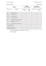
Страница 298: ...CCC 2011 Schneider Electric All rights reserved Schneider Electric 35 rue Joseph Monier 92506 Rueil Malmaison FRANCE Phone 33 0 1 41 29 70 00 Fax 33 0 1 41 29 71 00 www schneider electric com Publishing Schneider Electric Publication GTW EN T C40 03 2011 ...

Отзывы: