


13
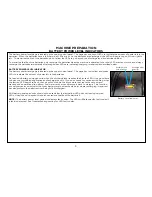
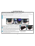
The pad drivers or brushes are attached by using the automatic on/off system. This valuable ingenuity removes the need for operators to
kneel or strain to attach the pad drivers or brushes.
First, start by placing the pad drivers or brushes on the floor in front of the S-Series mid-size scrubber.
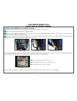
Quickly pulse the activation trigger
Position scrub head over pad
drivers or brushes
MACHINE PREPARATION
ATTACHING YOUR PAD DRIVERS OR BRUSHES TO THE S-SERIES MID-SIZE SCRUBBER - DISK HEAD
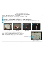
Lower the scrub head using the
foot pedal
Turn unit on using key switch
Turn the unit on using the power key switch.
Push or drive it into position so that the unit’s scrub head is centered over the pad drivers or brushes.
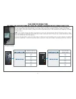
Utilize the foot pedal to lower the scrub deck down onto the pad drivers or brushes by depressing the pedal while shifting it to the right.
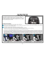
Once clear of the lower notch, lifting your foot will lower the scrub deck. Make sure that the shroud completely covers the pad drivers or
brushes in the lowered position. Should the shroud be resting on a portion of the pad drivers or brushes, the head isn’t centered and will
not attach properly.
The operation is completed by quickly pulsing the activation trigger. This will “click on” the pad drivers or brushes. If the pad drivers or
brushes do not quickly engage, do not continue pressing the activation trigger. Realign the scrub deck and try procedure again. When
you have the scrub deck aligned properly, you should see a noticeable drop of the scrub deck when lowered and the bristle skirt on the
shroud should almost be touching the floor.
1
2
3
4
1
2
3
4
Содержание S Series
Страница 45: ...45 FRAME ASSEMBLY WITH URETHANE WHEELS...
Страница 46: ...46 FRAME ASSEMBLY WITH FOAM FILLED WHEELS...
Страница 48: ...48 ON BOARD CHEMICAL INJECTION ASSEMBLY OPTIONAL...
Страница 49: ...49 BATTERY ASSEMBLY...
Страница 50: ...50 RECOVERY TANK ASSEMBLY...
Страница 51: ...51 SQUEEGEE ASSEMBLY S 24...
Страница 52: ...SQUEEGEE ASSEMBLY S 28 52...
Страница 53: ...SQUEEGEE ASSEMBLY S 32 53...
Страница 54: ...54 SQUEEGEE LINKAGE ASSEMBLY...
Страница 55: ...55 HEAD LIFT ASSEMBLY...
Страница 56: ...56 HEAD ASSEMBLY DRAWING 1 OF 2 S 24...
Страница 57: ...57 HEAD ASSEMBLY DRAWING 2 OF 2 S 24...
Страница 58: ...58 HEAD ASSEMBLY S 28 DISK...
Страница 59: ...59 HEAD ASSEMBLY S 32...
Страница 60: ...60 HEAD ASSEMBLY LOWER S 28 ORBITAL...
Страница 61: ...61 HEAD ASSEMBLY UPPER S 28 ORBITAL...
Страница 62: ...62 CONTROLS ASSEMBLY S 24...
Страница 63: ...63 CONTROLS ASSEMBLY S 28 S 32 DISK...
Страница 64: ...64 CONTROLS ASSEMBLY S 28 ORBITAL...
Страница 65: ...65 CONTROLS ASSEMBLY BATTERYSHIELDTM CHEMICAL INJECTION SYSTEM OPTIONAL...
Страница 66: ...66 ELECTRONICS ASSEMBLY S 24...
Страница 67: ...67 ELECTRONICS ASSEMBLY S 28 S 32 DISK...
Страница 68: ...68 ELECTRONICS ASSEMBLY S 28 ORBITAL...
Страница 69: ...69 ELECTRONICS ASSEMBLY BATTERYSHIELDTM...
Страница 70: ...70 CHARGER ASSEMBLY ON BOARD...
Страница 71: ...WIRING DIAGRAM S 24...
Страница 72: ...WIRING DIAGRAM S 28 S 32 DISK...
Страница 73: ...WIRING DIAGRAM S 28 ORBITAL...
Страница 74: ...WIRING DIAGRAM BATTERYSHIELD OPTIONAL 74...
Страница 75: ...WIRING DIAGRAM ON BOARD CHEMICAL INJECTION SYSTEM OPTIONAL 75...


