


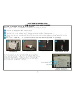
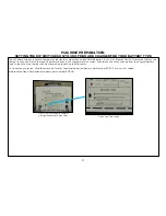


It is easy to gage the solution level by watching the fog-free solution sight gage at the rear of the
machine. Additionally, marks on the tank provide solution level indicators as a guide.
10
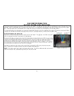
To prepare the machine for cleaning, the unit must be filled with cleaning solution.
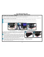
Rear hose fill port
NOTE:
Always use low-foam detergent. Introduce a small amount of defoaming liquid in the recovery tank
before starting work to prevent foam from being generated. Never use pure acids.
MACHINE PREPARATION
SOLUTION TANK
1
2
1
Water and cleaning agent can be added to the S-Series mid-size scrubber’s rear hose fill port located to
the left of the control panel.
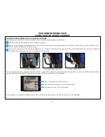
Liquid detergent should be added to the tank in the concentration and manner specified by the
manufacturer for an twenty two (22) gallon solution tank. The formation of excess foam could damage the
vacuum motor, so be sure to use only the correct amount of detergent. Water temperature should not
exceed 120°F (50°C).
Sight gage hose
4
4
6
The sight gage hose performs double-duty as the solution drain hose as well. You simply slide the
hose off the press fitting and lower the hose to a drain or mop sink.
Sight gage hose released from
press fitting
6
Solution level indicators
5
The bottom of the front fill port is also a full level indicator. Once you are able to see water at the base
of the opening, you have reached the full level.
3
There is also a front fill port that is able to accept hose or bucket filling.
The S-Series mid-size scrubber comes equipped with a fill port strainer to block debris from falling into
the solution tank.
Front fill port
2
5
3
Содержание S Series
Страница 45: ...45 FRAME ASSEMBLY WITH URETHANE WHEELS...
Страница 46: ...46 FRAME ASSEMBLY WITH FOAM FILLED WHEELS...
Страница 48: ...48 ON BOARD CHEMICAL INJECTION ASSEMBLY OPTIONAL...
Страница 49: ...49 BATTERY ASSEMBLY...
Страница 50: ...50 RECOVERY TANK ASSEMBLY...
Страница 51: ...51 SQUEEGEE ASSEMBLY S 24...
Страница 52: ...SQUEEGEE ASSEMBLY S 28 52...
Страница 53: ...SQUEEGEE ASSEMBLY S 32 53...
Страница 54: ...54 SQUEEGEE LINKAGE ASSEMBLY...
Страница 55: ...55 HEAD LIFT ASSEMBLY...
Страница 56: ...56 HEAD ASSEMBLY DRAWING 1 OF 2 S 24...
Страница 57: ...57 HEAD ASSEMBLY DRAWING 2 OF 2 S 24...
Страница 58: ...58 HEAD ASSEMBLY S 28 DISK...
Страница 59: ...59 HEAD ASSEMBLY S 32...
Страница 60: ...60 HEAD ASSEMBLY LOWER S 28 ORBITAL...
Страница 61: ...61 HEAD ASSEMBLY UPPER S 28 ORBITAL...
Страница 62: ...62 CONTROLS ASSEMBLY S 24...
Страница 63: ...63 CONTROLS ASSEMBLY S 28 S 32 DISK...
Страница 64: ...64 CONTROLS ASSEMBLY S 28 ORBITAL...
Страница 65: ...65 CONTROLS ASSEMBLY BATTERYSHIELDTM CHEMICAL INJECTION SYSTEM OPTIONAL...
Страница 66: ...66 ELECTRONICS ASSEMBLY S 24...
Страница 67: ...67 ELECTRONICS ASSEMBLY S 28 S 32 DISK...
Страница 68: ...68 ELECTRONICS ASSEMBLY S 28 ORBITAL...
Страница 69: ...69 ELECTRONICS ASSEMBLY BATTERYSHIELDTM...
Страница 70: ...70 CHARGER ASSEMBLY ON BOARD...
Страница 71: ...WIRING DIAGRAM S 24...
Страница 72: ...WIRING DIAGRAM S 28 S 32 DISK...
Страница 73: ...WIRING DIAGRAM S 28 ORBITAL...
Страница 74: ...WIRING DIAGRAM BATTERYSHIELD OPTIONAL 74...
Страница 75: ...WIRING DIAGRAM ON BOARD CHEMICAL INJECTION SYSTEM OPTIONAL 75...


