1. Remove the wire rope from the drum and wind onto
a cable reel as recommended by the wire rope man-
ufacturer. Power wash the hoist and all motor piping
to remove contamination that might enter open hose
and motor ports. Drain the gear oil from the hoist as
described in the Preventive Maintenance section of
this manual.
2. Remove the cable guard roller and cable tension
roller group. Stand the hoist up on the drum bearing
support end with the motor end up. Secure the hoist
in this position so that it does not fall over and cause
property damage or personal injury.
3. Tag and remove the hydraulic hoses that connect
the brake valve and motor manifold to the brake
release port.
4. Remove the four capscrews and lockwashers
securing the motor and lift the motor off the hoist.
Cover the motor ports to prevent contamination.
Remove the brake clutch assembly from the brake
cylinder. Disassembly of the brake clutch assembly
will be discussed in the “Brake Clutch Service” sec-
tion of this manual.
5. Remove the eight capscrews that secure the brake
cylinder to the motor side plate. Lift the brake cylin-
der out of the hoist and place on a clean work sur-
face. Disassembly of the brake cylinder will be dis-
cussed in the “Brake Cylinder Service “section of
this manual
.
6. Loosen the jam nut then remove the drum rotation
sensor from the motor side plate to prevent damage
to the sensor. Remove the ten capscrews that
secure the motor side plate to the base and lift the
side plate off the hoist drum.
7. Install two
½
in. NC lifting eyes into the tapped holes
in the drum closure and lift the closure out of the
drum.
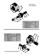
8. Remove the output planetary carrier assembly from
the drum.
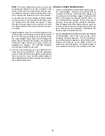
9. Grasp the input sun gear shaft and lift the input
planetary carrier assembly from the drum.
10. Lift the cable drum off the drum bearing support and
endplate assembly.
11. Thoroughly clean and inspect all components at this
time.
a. The drum bearings should roll freely and smooth-
ly. If they sound rough, clean again in solvent,
blow dry and inspect once more. If they still
sound rough, replace them.
b. Inspect sealing and bearing surfaces on drum
bearing support and brake cylinder for damage
that may prevent long seal and bearing life. If
damaged, replace or repair the components as
required.
c. Inspect the ring gear teeth for nicks, pitting or
excessive wear. To check for wear, place a
straight edge along the teeth such that the
straight edge spans from an unworn area, over a
worn area and again is supported by an unworn
area. Place feeler gauges under the straight
edge to measure the depth of the wear. If a small
ridge has been pushed up at the edge of the
worn area, you must first file down the ridge with
a flat mill file that spans across the worn area as
described for the straight edge. Replace the ring
gear if the wear in the gear contact area is
greater than .015 in. (.38 mm) when compared to
the unworn area of the teeth.
d. Conduct Magnetic Particle Inspection (MPI) of
the planet gears to check for any small stress
cracks that may not be visible to the naked eye.
Discard the gears if ANY cracks are found.
DISASSEMBLY PROCEDURE
The GHP30 hoist weighs approximately 1435 lb. (650
kg). Make certain lifting equipment has adequate
capacity. Using undersized or poorly maintained lift-
ing equipment may result in a dropped load, proper-
ty damage, injury or death.
CAUTION
The cable drum weighs approximately 350 lb. (160
kg). Make certain lifting equipment has adequate
capacity. Using undersized or poorly maintained lift-
ing equipment may result in a dropped load, proper-
ty damage or personal injury.
CAUTION
20


