background image

TROUBLE

PROBABLE CAUSE

REMEDY

F

Hoist “chatters” or surges while rais-
ing rated load.

G

1. Same as D2.

2. Hydraulic  oil  flow  to  motor  may  be

too low.

3. Controls being operated too quickly.

4. Hydraulic motor 2-speed control not

shifting correctly.

Same as remedies for Trouble D2.

Same as remedies for Trouble E2.

Conduct operator training as required.

Inspect  and  repair  motor  displacement
control.

The  wire  rope  does  not  spool
smoothly on the drum.

Check  mounting  distance  and  fleet
angle.  Reposition  hoist  as  required
to  achieve 

½

  to  1

½

  degree  fleet

angle.

Refer to “Hoist Installation”.

Consult  wire  rope  manufacturer  for
recommendation  of  wire  rope  that
best suits your application.

Replace  wire  rope  and  conduct
operator/rigger training as required.

1. The hoist may be mounted too close

to the main sheave, causing the fleet
angle to be more than 1

½

 degrees.

2. The hoist may not be mounted per-

pendicular  to  an  imaginary  line
between  the  center  of  the  cable
drum and the first sheave.

3. Could  possibly  be  using  the  wrong

lay  rope.  There  is  a  distinct  advan-
tage  in  applying  rope  of  the  proper
direction  of  lay.  When  the  load  is
slacked off, the several wraps on the
drum  will  stay  closer  together  and
maintain  an  even  layer.  If  rope  of
improper  lay  is  used,  the  coils  will
spread  apart  each  time  the  load  is
removed.  Then,  when  hoisting  is
resumed, the rope has a tendency to
criss-cross and overlap on the drum.
The  result  is  apt  to  be  a  flattened
and crushed rope.

4. The  hoist  may  have  been  over-

loaded,  causing  permanent  set  in
the wire rope.

19

H

Sensor does not read drum rotation
properly.

1. Sensor may need to be adjusted.

2. Sensor may not have correct supply

voltage.

3. Sensor may be defective.

Rotate drum slowly.

A. If  sensor  light  stays  on,  loosen  lock

nuts  and  slowly  turn  the  sensor
CCW until sensor light blinks on and
off.  Continue  turning  sensor  1/4  to
1/2  CCW  after  light  blinking  starts
and  tighten  lock  nuts  until  snug  to
avoid damage to the sensor.

B. If  sensor  light  does  not  come  on  or

blink,  loosen  locknuts  and  slowly
turn the sensor CW until sensor light
blinks  on  and  off.  Continue  turning
sensor  1/4  to  1/2  CW  after  light
blinking  starts  and  tighten  locknuts
until  snug  to  avoid  damage  to  sen-
sor.

Test  voltage  at  sensor  plug,  pin1,
brown  wire.  Voltage  must  be  9-24
volts  DC.  If  voltage  is  too  low  or  0
volts, test electrical harness for open
circuit.

Replace  sensor.  Adjust  sensor  as
described above in H1.

Содержание BRADEN PD21A Series

Страница 1: ...PLANETARY HOIST INSTALLATION MAINTENANCE AND SERVICE MANUAL LIT2158 R2 9 2007 Printed in U S A PACR WINCH DIVISION P O BOX 547 BROKEN ARROW OK U S A 74013 PHONE 918 251 8511 FAX 918 259 1575 www pacc...

Страница 2: ...8 INSTALLATION 9 WIRE ROPE INSTALLATION 9 HOIST OPERATION 11 HYDRAULIC CIRCUIT 12 RECOMMENDED FASTENER TORQUE 12 PREVENTIVE MAINTENANCE 13 RECOMMENDED GEAR OIL 14 OIL SAMPLING AND ANALYSIS 15 TROUBLE...

Страница 3: ...stood Some pictures in this manual may show details or attachments that are different from your hoist Also some com ponents have been removed for illustrative purposes Continuing product improvement m...

Страница 4: ...ds or kilograms on the first layer of cable The maximum rating for any particular hoist is based on maintaining an acceptable structural design factor and service life Certain combinations of drum gea...

Страница 5: ...to clean oil or perform any mainte nance on a machine with the engine or prime mover running unless instructed to do so in this manual 20 Never operate hoist controls unless you are proper ly positio...

Страница 6: ...y from 0800 to 1630 hours CST by fax at 918 259 1575 or via the internet at www paccarwinch com for the latest avail able information CAUTION This emblem is used to warn against potential or unsafe pr...

Страница 7: ...N The dual brake system consists of a dynamic brake sys tem and a static brake system The dynamic brake system has two operating compo nents 1 Brake valve assembly 2 Hydraulic motor The brake valve is...

Страница 8: ...ot rotate until sufficient pilot pressure is present to open the brake valve Figures 3 4 The fric tion brake within the hoist will completely release at a pressure lower than that required to open the...

Страница 9: ...Base Components Drum Gear Train Motor Brake Valve Brake Cylinder Brake Clutch Support End Bracket Detail PD21A COMPONENTS 8...

Страница 10: ...mm 5 Hydraulic lines and components that operate the hoist should be of sufficient size to assure minimum back pres sureatthehoistmotorports Toinsureadequatestaticbrake load holding ability back pres...

Страница 11: ...mine the proper wedge size It is important that the wire rope have the proper ten sioning when it is installed on the drum When the wire rope is first installed you should operate the hoist with light...

Страница 12: ...ke operation Our tests indicate that excessive ly heavy or thick gear oil may contribute to intermit tent brake slippage Make certain that the gear oil viscosity used in your hoist is correct for your...

Страница 13: ...NOTE The hydraulic circuit shown below is representative of typical Braden hoists Options and accessory equip ment may result in changes to the circuit shown If there are any questions regarding the h...

Страница 14: ...the full length of wire rope rigging and all sheaves according to the wire rope and crane man ufacturer s recommendations 6 A warm up procedure is recommended at each start up and is mandatory at amb...

Страница 15: ...aring support It is important to keep the vent plug clean and unob structed Whenever the gear oil is changed the vent plug should be removed cleaned in solvent and reinstalled Do not paint over the ve...

Страница 16: ...n property damage personal injury or death Early detection of accelerated component wear allows the scheduling of corrective maintenance and can reduce in operation failures and costly down time Takin...

Страница 17: ...ug with a hole drilled through it located behind the pilot port fitting on the brake valve If it becomes plugged it will prevent the pilot pressure from the manifold from opening the brake valve If it...

Страница 18: ...ith rec ommended planetary gear oil listed in Preventive Maintenance Brake clutch may be damaged or worn Disassemble and inspect brake clutch as described in Over running Clutch Service 1 Excessive sy...

Страница 19: ...charts for additional information Perform rigging service as rec ommended by crane manufac turer Same as remedies for Trouble D1 Thoroughly clean exterior and flush interior Fill drain to proper level...

Страница 20: ...n the load is slacked off the several wraps on the drum will stay closer together and maintain an even layer If rope of improper lay is used the coils will spread apart each time the load is removed T...

Страница 21: ...un gear shaft and lift the input planetary carrier assembly from the drum 10 Lift the cable drum off the drum bearing support and endplate assembly 11 Thoroughly clean and inspect all components at th...

Страница 22: ...f 19 rollers separat ed by a spacer ring in the output planet gears Place a second thrust washer on top of the planet gear Carefully slide the planet gear with bearing rollers and thrust washers into...

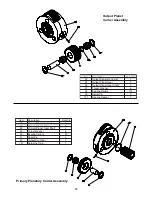
Страница 23: ...ring Rollers 114 39 Spirol Pin 3 101 Bearing Spacer 3 Output Planet Carrier Assembly Primary Planetary Carrier Assembly Item Description Quantity 26 Primary Planetary Carrier 1 27 Primary Planet Gear...

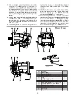
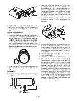
Страница 24: ...tall the remaining bearing 44 and retaining ring 47 Make certain all retaining rings are fully seated in the grooves Apply a liberal amount of hoist gear oil to the over running brake clutch assembly...

Страница 25: ...n back up ring 6 from the cylinder 4 Remove the pressure plate 7 and the springs 9 and spring spacer 10 Clean and Inspect 1 Thoroughly clean all the brake cylinder parts at this time Check sealing sur...

Страница 26: ...n top of the last steel brake disc 4 To check brake stack height place pressure plate 7 on top of brake spacer Hold pressure plate down firmly by hand and measure gap in three places between motor ada...

Страница 27: ...nstall the four capscrews and lockwashers After the capscrews make contact with the motor adapter evenly tighten them one turn at a time until the motor adapter is drawn tight against the brake cylind...

Страница 28: ...is even with the outside surface of the closure Install a new o ring 68 into the groove in the out side diameter of the closure Lubricate the outside diameter of the closure with multi purpose grease...

Страница 29: ...is complete check all fas teners and hydraulic fittings to make certain they have been properly tightened Refill the hoist with the recommended planetary hoist gear oil 17 Before returning the hoist t...

Страница 30: ...ce from the brake release BR port using a 5 32 in Allen wrench 2 Remove the spool spring retainer 3 and spool spring 11 Check spring free length Replace spring if less than 1 15 16 in 49 2 mm long 3 R...

Страница 31: ...o rings to return to their original size after being stretched 3 Lubricate the spool and damper piston o rings with hydraulic oil Carefully install the damper piston into the spool 4 Lubricate the sp...

Отзывы: