1. Thoroughly clean the machined surfaces of the cast
base (61). Make sure the tapped holes, end plate
and bottom mounting surfaces are free of paint and
rust. Place the base on a clean, sturdy work sur-
face.
2. If the drum bearing support (41) was removed from
the end plate, install it into the end plate with the
vent port near the top and the word “LEVEL” read-
ing correctly in a horizontal plane. Install the bearing
support/end plate sub-ssembly onto the base using
capscrews and washers (60 & 62). Evenly tighten
the capscrews to 180 lb.-ft. (244 N-m) torque. Lay
the base and end plate over such that the drum
bearing support faces up.
3. Install a new bearing into the drum if replacement is
necessary, making certain to press it against the
shoulder in the bottom of the bearing bore. Coat the
outside diameter of a new seal with a good grade of
sealant. Turn the spring side of the seal toward the
bearing, and press the seal into the seal bore, leav-
ing it flush with the surface of the drum bore.
4. Turn the drum over, and set it down on the bearing
support. Be careful not to damage the seal when
lowering the drum onto the bearing support.
5. Apply a light coat of oil-soluble grease to the pri-
mary sun gear thrust pad (102) then install it into the
recess in the primary planet carrier(s).
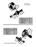
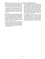
6. Install the primary planetary carrier assembly (3)
into the drum. Rotate the carrier as you mesh the
planet gears with the ring gear machined in the
drum.
7. Apply a light coat of oil-soluble grease onto the
thrust washer (66) and install the thrust washer onto
the primary planet carrier. Install the input sun gear
(55) into the primary planetary carrier.
8. Install the output planetary carrier assembly (4) into
the drum. Rotate the carrier slowly as you mesh the
planet gears with the ring gear.
9. Install a new bearing (64) into the drum closure (56)
if replacement is necessary, making certain to press
it against the shoulder in the bottom of the bearing
bore. Lightly coat the outside diameter of a new
drum seal (70) with non-hardening sealant. Install
the seal into the closure with the garter spring
toward the bearing. Press the seal into the bore until
it is even with the outside surface of the closure.
Install a new o-ring (68) into the groove in the out-
side diameter of the closure. Lubricate the outside
diameter of the closure with multi-purpose grease
and install the closure into the drum. Push the clo-
sure into the drum until it bottoms against a shoul-
der machined into the drum. If the closure bottoms
on the output planetary carrier before it bottoms in
the drum, you may have installed the primary thrust
pad upside down and the gear train must be
removed to check this condition. Do not proceed
until this is resolved.
10. Place the motor side end-plate (40) onto the drum
and loosely install the ten capscrews and washers
(60 &62) that secure the end-plate to the base. Do
not fully tighten the capscrews at this time.
11. Use multi-purpose grease to lubricate the bearing
journal, seal journal and mounting flange surfaces
of the brake cylinder housing (2). Carefully install
the brake cylinder into the drum closure. It may be
necessary to slightly rotate the brake housing to
engage the splines of the housing with the output
planet carrier.
12. Secure the brake cylinder to the end-plate with eight
capscrews and washers (51 & 52). Tighten the cap-
screws to 80 lb.-ft. (109 N-m) torque. Tighten the
fasteners in a cross pattern to maintain even clamp
load. Install the over-running brake clutch assembly
(1) into the brake cylinder assembly. If the splines of
the outer race and the brake discs do not line up,
install a hydraulic adapter into the brake release
port and connect a hand pump to the adapter. Apply
approximately 600 PSI (4150 kPa) to release the
static brake. When released, rotate the brake clutch
assembly back-and-forth to align the discs. The
brake clutch assembly must be installed with the
long shoulder of the outer race toward the motor
and the internal retaining ring inside the inner race
must be offset toward the hoist drum to make room
for the motor shaft. The internal retaining ring
should seat against the input sun gear when cor-
rectly installed. Finish tightening the end plate to
base capscrews, installed in step 10 above, to 160
lb.-ft. (217 N-m) torque.
HOIST ASSEMBLY
(Refer to illustration on page 8)
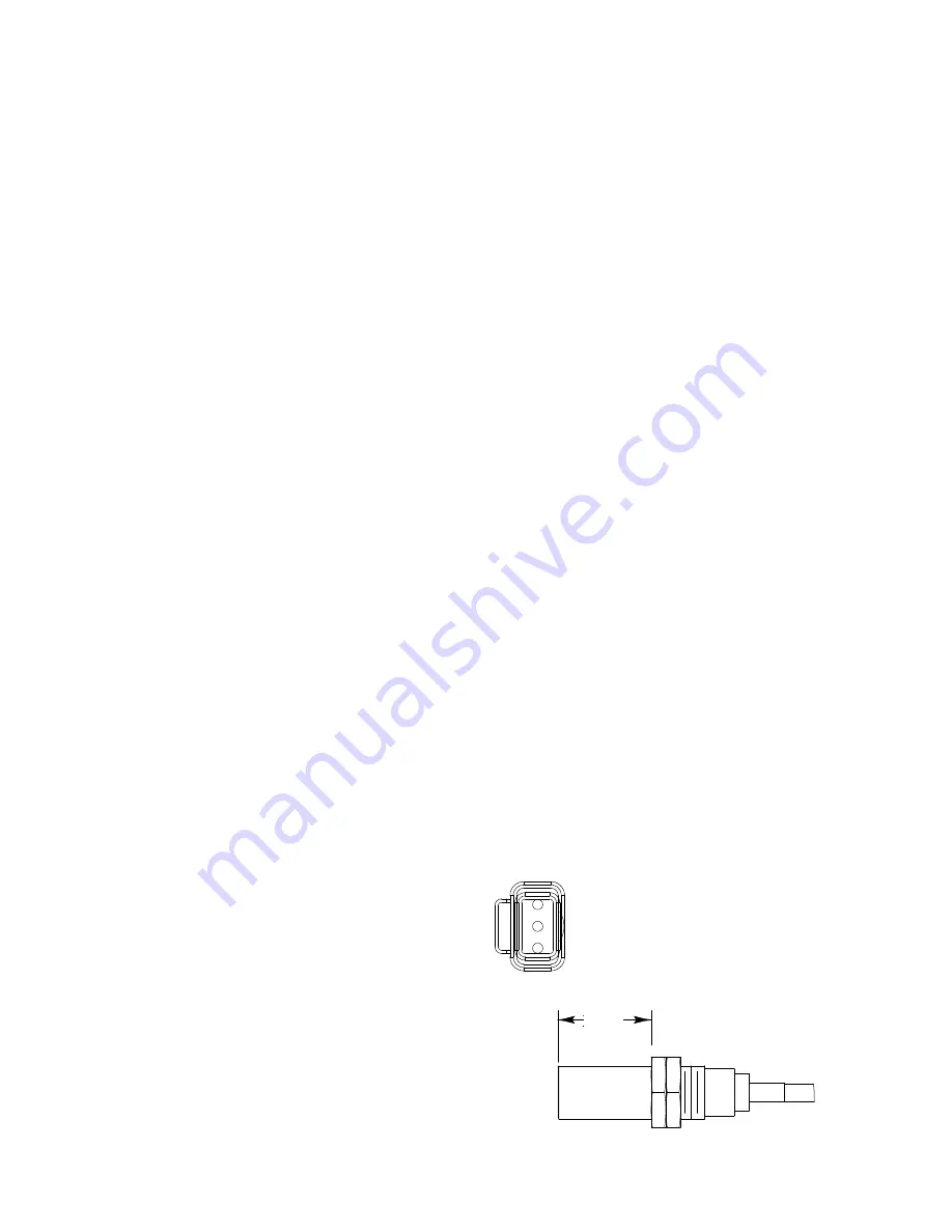
Adjust sensor nut to 1.21 in. (30.7 mm)
before installation into motor end plate
27
Sensor Connector
3
2 (-)
1 (+)
Pin 3 = Ground (Blue)
Pin 2 = Output (Black) (-)
Pin 1 = Supply (Brown) (+)
1.21


