CDV Construction Manual – Issue 3
Page 23
10.4
S
CAN MODE
1.
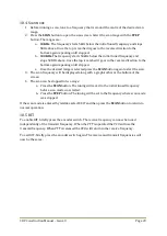
Before running a scan, tune to a frequency that is around the centre of the desired scan
range.
2.
Press the
SCAN
button to open the scan screen. Select the scan range with the
STEP
button. The ranges are:
a.
10KHz
. The frequency starts 5kHz below the initial tuned frequency and stops
5KHz above. Once the top is reached it goes in the reverse direction to the
bottom again repeating until stopped.
b.
100KHz
. The frequency starts 50kHz below the initial tuned frequency and
stops 50KHz above. Once the top is reached it goes in the reverse direction to the
bottom again repeating until stopped.
c.
Once the desired range is selected press the
SCAN
button again to start the scan.
3.
The scan frequency will be displayed along with a graphical bar at the bottom of the
screen.
4.
The scan can be stopped in two ways:
a.
Press the
SCAN
button. The tuning will revert to the initial tuned frequency
before scan mode was started.
b.
Press the
STEP
button. The tuning will be set to the frequency where scan mode
was stopped.
If the scan mode is entered by mistake select EXIT and then press the
SCAN
button to return to
normal operation.
10.5
RIT
To enable RIT, briefly press the encoder switch. The receive frequency can now be tuned
independently of the transmit frequency. When the PTT is operated the VFO will use the
transmit frequency. When PTT is released the VFO will return to the receive frequency.
To exit RIT, briefly press the encoder switch again. The receive and transmit frequencies will
now be the same.
Содержание CDV
Страница 1: ...CDV Construction Manual Issue 3 Page 1 CDV COMPACT DIGITAL VFO CONSTRUCTION MANUAL ...
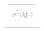
Страница 8: ...CDV Construction Manual Issue 3 Page 8 Figure 1 Microcontroller and power supply schematic ...
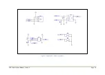
Страница 9: ...CDV Construction Manual Issue 3 Page 9 Figure 2 Si5351A Clock generator schematic ...
Страница 10: ...CDV Construction Manual Issue 3 Page 10 Figure 3 Display and controls schematic ...
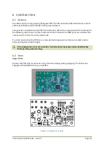
Страница 30: ...CDV Construction Manual Issue 3 Page 30 Figure 11 Attenuator filter board fitted to the CDV ...

