CDV Construction Manual – Issue 3
Page 15
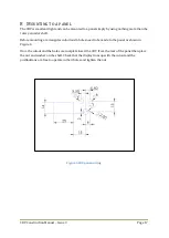
Step 6: OLED
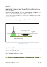
The OLED is inserted into the solder side of the PCB using the integral 4 pin male header.
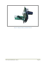
Position the OLED so that its front face sits just behind the rear of the panel where the CDV is
mounted. See Figure 5.
Solder one pin and double check the clearance and ensure that the OLED is parallel to the PCB. If
necessary melt the solder and reposition, then solder the remaining pins.
It may also be necessary to trim the top of the header pins if a metal panel is used to avoid the
possibility of short circuits.
If the OLED is installed close to the main PCB, it may be necessary to trim the pins on the 2pin
JST connectors to avoid them touching the back of the OLED.
Figure 5 OLED mounting
Step 7: Knobs and caps
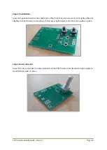
Push the small long actuator knobs onto the pushbuttons. Take care to avoid excessive sideways
force that could damage the switch.
The encoder knob slides onto the ‘D’ style encoder shaft. A small amount of lubrication, such as
Silicone spray, makes it easier to slide on and off.
The knob must be removed from the shaft before mounting the CDV to a panel.
Содержание CDV
Страница 1: ...CDV Construction Manual Issue 3 Page 1 CDV COMPACT DIGITAL VFO CONSTRUCTION MANUAL ...
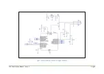
Страница 8: ...CDV Construction Manual Issue 3 Page 8 Figure 1 Microcontroller and power supply schematic ...
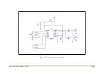
Страница 9: ...CDV Construction Manual Issue 3 Page 9 Figure 2 Si5351A Clock generator schematic ...
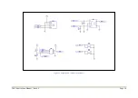
Страница 10: ...CDV Construction Manual Issue 3 Page 10 Figure 3 Display and controls schematic ...
Страница 30: ...CDV Construction Manual Issue 3 Page 30 Figure 11 Attenuator filter board fitted to the CDV ...


