CDV Construction Manual – Issue 3
Page 16
7
T
ESTING
7.1
G
ENERAL
The CDV microcontroller has been programmed and the board given a functional check before
being dispatched. This means the CDV should work first time, however the following procedure
provides a quick check that the CDV is operating correctly once assembled.
If there are problems look for errors with the soldering of the connectors, controls and OLED. If
there is no sign of life check that the power supply is connected with the correct polarity. No
damage should result as the CDV has reverse polarity protection.
7.2
P
OWER ON
1.
Connect the 4 pin connector red wire to the power supply positive lead. Connect the
black wire to the power supply negative lead. The power supply can be between 5 and
15V DC.
2.
Turn on the supply and note the current. It should be around 30mA. If it’s far from this
turn off immediately and look for problems.
3.
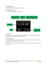
The OLED should display the opening banner along with the firmware version number,
then after a short period display the operating screen.
7.3
C
ONTROLS
1.
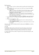
Rotate the encoder knob and check that the frequency can be changed up and down.
2.
Press the
SCAN
button and check that Scan mode menu appears, and select Exit with the
STEP
button to return to the operating screen.
3.
Press the
STEP
button and check that the frequency step can be changed.
4.
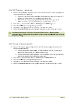
Press and hold the encoder button for a few seconds and check that the Set-up screen is
displayed. Select FULL with the
STEP
button and step through the menus using the
SCAN
button and return to the operating screen.
5.
Connect the 4 pin connector white (blue) wire to the power supply positive lead. The
RX/TX display should change state.
6.
Connect the 4 pin connector yellow (grey) wire to the power supply positive lead. The
USB/LSB display should change state.
7.4
O
UTPUT
S
IGNALS
1.
Terminate the outputs with a 50 ohms resistor (two 100 ohm in parallel) and place an
oscilloscope across the load. Verify a square wave output signal with an amplitude of
around 2V pk-pk at the expected frequency.
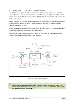
The fixed output is disabled by default so it needs to be enabled in Set-up to view its
output.
If an optional add-on board is installed, then the output will be conditioned. The
amplitude depends on the attenuator fitted and the waveform will be closer to a
sine wave.
Содержание CDV
Страница 1: ...CDV Construction Manual Issue 3 Page 1 CDV COMPACT DIGITAL VFO CONSTRUCTION MANUAL ...
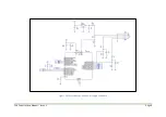
Страница 8: ...CDV Construction Manual Issue 3 Page 8 Figure 1 Microcontroller and power supply schematic ...
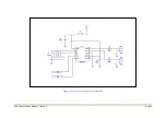
Страница 9: ...CDV Construction Manual Issue 3 Page 9 Figure 2 Si5351A Clock generator schematic ...
Страница 10: ...CDV Construction Manual Issue 3 Page 10 Figure 3 Display and controls schematic ...
Страница 30: ...CDV Construction Manual Issue 3 Page 30 Figure 11 Attenuator filter board fitted to the CDV ...

