CDV Construction Manual – Issue 3
Page 14
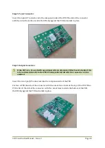
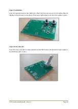
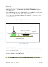
Step 4: Pushbuttons
Insert the pushbuttons into the solder side of the PCB. It may be necessary to straighten the pins
slightly so they fit easily. Ensure they sit flat and at right angles to the PCB, then solder in place.
Step 5: Rotary Encoder
Insert the rotary encoder into the solder side of the PCB. Ensure it sits flat and at right angles to
the PCB then solder in place.
Содержание CDV
Страница 1: ...CDV Construction Manual Issue 3 Page 1 CDV COMPACT DIGITAL VFO CONSTRUCTION MANUAL ...
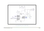
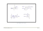
Страница 8: ...CDV Construction Manual Issue 3 Page 8 Figure 1 Microcontroller and power supply schematic ...
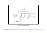
Страница 9: ...CDV Construction Manual Issue 3 Page 9 Figure 2 Si5351A Clock generator schematic ...
Страница 10: ...CDV Construction Manual Issue 3 Page 10 Figure 3 Display and controls schematic ...
Страница 30: ...CDV Construction Manual Issue 3 Page 30 Figure 11 Attenuator filter board fitted to the CDV ...


