background image

8

The control station is pre-assembled and leak tested
at works.
The pump and the electric sensor attachment to pipe
are cabled and joined to the connection cable via the
plug-in connector. 
The control station is supplied for left hand side con-
nection. 
For right hand side connection, turn the complete con-
trol  station  vertically.  Now  turn  pump  in  such  a  way
that the motor is pointing forward. Loosen collar nuts
at the pump. Turn pump by 180° and re-tighten collar
nuts firmly.
Screw  control  station  firmly  onto  the  stainless  steel
distributor/collector. 

When 

installing 

the

distributors/collectors with 2 and 3 heating circuit con-
nections, mount the bracket supplied with the control
station as additional bracket (see illustr. 5.1 and part
6, illustr.6.1).
When  mounting  the  control  station  inside  a  cabinet,
please observe paragraph 4.2 “Dimensions/connection
size”.
To mount the temperature controller (part 3, illustr. 6.1),
remove the protection caps of the three-way valve. 
Fix the sensor attachment to pipe (part 2, illustr. 6.1)
onto the body of the supply using the elastic fastening
strap (part 4, illustr. 6.2). Set sensor for attachment to
pipe about 5 K above the nominal value of the maxi-
mum flow temperature. 
Connection to the sensor attachment to pipe, via the
pre-assembled  cabling,  is  carried  out  by  plugging  it
into the pump plug. 

The  power  supply  must  be  switched  off  before
work commences.

Observe warning advice under paragraph 2
(safety notes)!

– Do  not  use  any  lubricant  or  oil  when  installing

the valve as these may destroy the seals. If ne-
cessary, all dirt particles and lubricant or oil re-
sidues must be removed from the pipework by
flushing the latter.

– When  choosing  the  operating  fluid,  the  latest

technical development has to be considered (e.g.
VDI 2035).

– Please protect against external forces (e.g. im-

pacts, vibrations etc.).

After installation, check all installation points for le-
aks.

7 Operation

7.1 Bleeding the system

Before initial operation, the system must be filled and
bled with due consideration of the permissible opera-
ting pressures.

7.2  Correction  factors  for  mixtures  of  water  and
glycol

The correction factors of the manufacturers of the an-
tifreeze  liquids  have  to  be  considered  when  setting
the flow rate.

8 Accessories

The Oventrop ball valves:
– 1406383  DN 20 G

3

4

F x G1 M

– 1406384  DN 25 G1 F x G1 M
can be screwed onto the control station for the isola-
tion of the supply and the return pipe. 

9 Maintenance

The control station is maintenance-free.

10 Warranty

Oventrops  warranty  conditions  valid  at  the  time  of
supply are applicable.

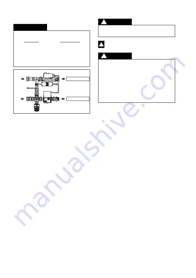
– The supply at the control station is always loca-

ted at the top and the return at the bottom.
This  must  be  strictly  observed  when  installing
the distributors (see illustr. 6.2)!

– The installation and operating instructions of the

stainless  steel  distributors/collectors  “Multidis
SF” must be observed.

Illustr. 6.2 Flow direction

6.2 Installation of “Regufloor H”

Supply distributor

Return collector

Supply

Return

DANGER

!

PRECAUTION

!

ATTENTION

!

Содержание Regufloor H

Страница 1: ...nnen wenn die Sicherheitsma nahmen nicht befolgt werden 1 Allgemeine Hinweise 1 1 Informationen zur Einbau und Betriebsanleitung Diese Einbau und Betriebsanleitung dient dem ge schulten Fachpersonal...

Страница 2: ...frei aufbewah ren Keinen aggressiven Medien oder Hitzequellen aus setzen Vor Sonneneinstrahlung und berm iger mechani scher Ersch tterung sch tzen Lagertemperatur 20 C bis 60 C relative Luftfeuchtigke...

Страница 3: ...nd zwei Ausg nge Das durchflie ende Medium wird je nach Stellung des Ventiltellers von einem Ausgang auf den anderen umgelenkt oder bei Zwischenstellungen zwi schen den Ausg ngen aufgeteilt Der Temper...

Страница 4: ...en Warnhinweise unter Abschnitt 2 Sicherheits hinweise beachten Bei der Montage d rfen keine Fette oder le verwendet werden da diese die Dichtungen zer st ren k nnen Schmutzpartikel sowie Fett und lre...

Страница 5: ...or serious injury if the safety guidelines are not obser ved ATTENTION indicates a possible damage to property which may occur if the safety guidelines are not observed 1 General information 1 1 Info...

Страница 6: ...ect sunlight and mechanical agitation Storage temperature 20 C up to 60 C max relative humidity of air 95 3 3 Packaging Packaging material is to be disposed of environmen tally friendly 4 Technical da...

Страница 7: ...one inlet port and two outlet ports Depending on the position of the valve disc the direction of flow is diverted from one outlet port to the other or in case of intermediate positions it is di vided...

Страница 8: ...serve warning advice under paragraph 2 safety notes Do not use any lubricant or oil when installing the valve as these may destroy the seals If ne cessary all dirt particles and lubricant or oil re si...

Страница 9: ...es d g ts mat riels qui peuvent r sulter de la non obser vation des consignes de s curit 1 G n ralit s 1 1 1 1 Informations sur la notice d installation et d utilisation Cette notice d installation et...

Страница 10: ...agents agressifs ou des sources de chaleur Prot ger contre le rayonnement solaire et les vibra tions m caniques excessives Temp rature de stockage 20 C 60 C humidit relative de l air 95 max 3 3 Embal...

Страница 11: ...t trois voies poss de une entr e et deux sorties Selon la position du clapet le fluide circulant est dirig d une sortie vers l autre ou dans les positions interm diaires r parti entre les deux sorties...

Страница 12: ...ctrique de la station de r gulation avant toute intervention Les signalements de danger dans le para graphe 2 Consignes de s curit sont re specter Ne pas utiliser des graisses ou huiles lors du montag...

Страница 13: ...ZIONE indica possi bili danni materiali che possono insorgere se le misure di sicurezza non vengono rispettate 1 Note generali 1 1 Informazioni per le istruzioni di montaggio e di funzionamento Queste...

Страница 14: ...prodotti aggressivi o a fonti di calore Proteggere dai raggi solari e da vibrazioni meccani che eccessive Temperatura di stoccaggio 20 C fino a 60 C Umidit relativa max 95 3 3 Imballaggio Tutti i mate...

Страница 15: ...rescamento a superfici radianti La valvola a tre vie dispone di una entrata e di due us cite A seconda della posizione del piattello della val vola il fluido viene deviato da un uscita all altra oppur...

Страница 16: ...ti prodotti potrebbero danneggiare le guarnizioni di tenuta Eliminare tramite risciacquo le eventuali particelle di sporco o residui di grasso e olio dalle tubazioni Nella scelta del fluido necessario...

Страница 17: ...17 Premium Armaturen Systeme Regufloor H RU 1 17 2 18 3 18 4 18 5 19 6 19 7 20 8 20 9 20 10 20 1 1 Regufloor H 1 1 1 1 2 1 2 1 4 www oventrop com...

Страница 18: ...18 3 3 1 3 2 Regufloor H 20 60 C 95 3 3 4 4 1 p 6 0 75 t 90 C t 50 C 20 50 C 20 90 C kvs 4 15 200 75 VDI 2035 2 2 1 Regufloor H 2 2...

Страница 19: ...19 5 1 Regufloor H 145 4 1 4 2 4 1 5 5 1 6 1 6 6 1 1 2 3 20 50 C 4 5 6 Regufloor H p v p c 60 C 120 200 67 G 1 G 1 G 1 G 1 316 100 134 145 2 4 1 6 5 3...

Страница 20: ...20 180 2 3 5 1 6 6 1 4 2 3 6 1 2 6 1 4 6 1 5K 2 VDI 2035 7 7 1 7 2 8 Oventrop 1406383 20 G3 4 x G1 1406384 25 G1 x G1 9 10 Oventrop 6 2 Multidis SF 6 2 6 2 Regufloor H...

Отзывы: