KV
Ulkol. °C
Menovesi °C
Valinta
Automaattiohj
L2
Ulkol. °C
Menovesi °C
Valinta
Automaattiohj
KV
Ulkol. °C
Menovesi °C
Valinta
Automaattiohj
L2
Ulkol. °C
Menovesi °C
Valinta
Automaattiohj
OUMAN EH-203
OUMAN EH-203
HW
Automatic
H2
Automatic
OUMAN EH-203
OUMAN EH-203
Ajan asetus
In Ouman EH-203 the regulator is controlled by many different
settings.
By browsing you can see which settings you have in use.
Browsing and setting changes occur in the following way:
Settings are selected according to sensor connections
and relay control modes (e.g., is a relay controlling the oil
burner or pump or is the relay temperature controlled see p. 26-27).
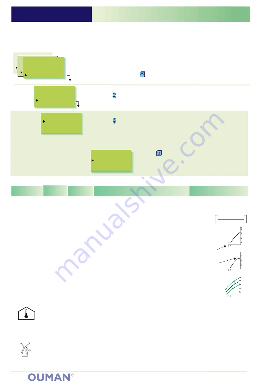
Use the
button to move to domestic hot water
regulating circuit (HW). Press
the or
button to change the setting.
Press
Exit with
Press
OK.
-
+
OK.
ESC.
Changing the heating regulating circuit setting:
OK.
OK.
ESC.
Press the
button to move the cursor to the setting that you want to
change. Press
the
or
button to change the setting. Press
Exit with
Press
-
+
Press the
button to move cursor to "Settings". Press
OK.
Room temperature setting, which user has set.
The supply water temperature drop, determined
by the clock program or the external home/away
switch. (Room compensation takes a desired drop
in room temperature into account)
Minimum allowed supply water temperature.
Set the minimum limit for floor heating circuit tiled
floors between 20...25°C, to ensure a comfortable
temperature and removal of moisture in the
summer.
Maximum allowed supply water temperature.
The maximum limit prevents the temperature in
the heating circuit from rising too high, preventing
damage to pipes and surface materials. If, e.g.,
the characteristic heating curve setting is
incorrect, the maximum limit prevents excessively
hot water from entering the network. Set the
upper limit for floor heating between 35...40°C.
A parallel shift occurs when a change in supply
water temperature occurs at each adjustment
point.
Room compensation ratio: If the room
temperature is different than what it is set at, the
room compensation corrects the supply water
temperature. (Eg.) If the room compensation is 4
and the room temperature has risen 1,5 °C above
the setting, the regulator drops the supply water
temperature 6 °C (4x1,5 °C =6 °C)
A house cools down in windy weather. In that
case the wind compensation raises the supply
water temperature. The reading indicates the
maximum amount that the wind compensation
can raise the supply water temperature. Wind
compensation can also be used as a general
compensation, e.g., sun compensation. In that
case give a negative setting!
5.0...45.0°C
0...35°C
5...95°C
20...125°C
-15...+15°C
0.0...7.0°C
-7...7°C
21,5°C
0°C
15°C
70°C
0°C
4.0°C
0°C
Room temp.
Temp drop
Min. limit
Max. limit
Parall.shift
Room compens.
Wind.compens.
(w)
(supply water)
During temp. drop period
regulator use the calculated
room temp. setting, which is
INFORMATION ABOUT SETTINGS:
80
65
50
35
20
20 0 -20 °C
Minimum limit
SETTINGS
Browsing, making changes
HW Settings
°C
DomHot wat.
55.0
80
65
50
35
20
20 0 -20 °C
Maximum limit
6
H1 Select
Heating curve
Settings
Measurements
H1 Settings
Room temp.
Temp drop(w)
Min. limit
Max. limit
RoomCompens.
Wind compens.
Sun compens.
Pre-increase
Autumn dry
Valve close
21.5
15
70
4,0
0
2
70
50
0
0
0
19
55
Burner ON
ON
El.Heater
R1 Temp.lim.
Press
ESC
until the display no longer changes.
You are then in the "Selection" display shown in the adjoining picture.
OPERATING INSTRUCTION:
Press
OK.
Press the
button to move from one regulating circuit to
the next (H1, H2, HW).
Changing the domestic hot water temperature:
H1
Outdoor
°C
SupplyTemp
°C
Selection
Automatic
-15
52
Room sensor
(TMR) must be
connected (H1:meas.3, H2:
meas. 6, or net).
An appropriate room
compensation ratio for floor
heating is usually between 1.5
- 2.0°C.
Room temp. -
Temp drop(w)
Room compens.
Wind sensor
must be
connected, the same sensor
for regul. circuits H1 and H2
(meas. 6 or net).
Settings:
Factory
settings: Range:
Explanation:
Attention!
Parallel shifts
80
65
50
35
20
20 0 -20 ÉC
80
65
50
35
20
20 0 -20 ÉC
Содержание EH-203
Страница 11: ...Liite 1 Suunniteltavan levyn piirikaavio...
Страница 12: ...Liite 2 Suunniteltavan levyn osaluettelo Kuvassa vasemmalla liitin X1 oikealla liitin X2 X3...
Страница 18: ...X X X X X Goal X X X X Start X X...
Страница 84: ...LIITE 4 Piirikaavio...
Страница 85: ...LIITE 5 OSASIJOITTELUKUVA...


