03/2010
B500 | B500-S
Page 83
List of Figures
List of figures
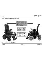
Fig. 1
Signage on the B500 / B500-S .................. 94
Fig. 2
Folding size ............................................. 100
Fig. 3
Main components of the B500 / B500-S ... 102
Fig. 3.1 Anti-tipper B500 ...................................... 103
Fig. 4
Fuse holder ............................................. 103
Fig. 5
Release strap for the backrest ................ 104
Fig. 6
Removing the side panel ......................... 105
Fig. 7
Adjusting the height of the armrest .......... 105
Fig. 8
Adapting the control panel ...................... 106
Fig. 9
Footrest lock ........................................... 107
Fig. 10 Adjusting the lower leg length .................. 108
Fig. 11 Footplates flipped up ............................... 109
Fig. 12 Footrests removed ................................... 109
Fig. 13 Control panel .......................................... 110
Fig. 14 Display with all its symbols ...................... 112
Fig. 15 Brake release .......................................... 119
Fig. 16 Locking the brake .................................... 119
Fig. 17 Snap lock on safety strap ........................ 120
Fig. 18 Batteries ................................................. 121
Fig. 19 Mechanical seat tilt adjustment ............... 126
Fig. 20 Electric seat tilt adjustment ...................... 127
Fig. 21 Mechanical back angle adjustment ......... 127
Fig. 22 Electric back angle adjustment ................ 128
Fig. 23 Lift seat in raised position (B500-S) ......... 130
Fig. 24 Snail symbol indicating creep speed ....... 131
Fig. 25 Cross bolt locked in the holding device .... 131
Fig. 26 Front lights on the side panel ................... 132
Fig. 27 Changing the front lights ......................... 132
Fig. 28 Replacing the direction indicator lamp ..... 133
Fig. 29 Rear light without lamp cover .................. 134
Fig. 30 Release bolt on the battery drawer .......... 135
Fig. 31 Caster swivel lock engaged and released ..135
Fig. 32 Mechanically elevating footrest ................ 136
Fig. 33 Elevated footrest ..................................... 137
Fig. 34 Height adjustment of control panel holder . 137
Fig. 35 Swing-away control panel holder ............. 138
Fig. 36 External mileage counter ......................... 138
Fig. 37 Applying the lap belt ................................ 141
Fig. 38 Headrest mounting kit ............................. 142
Fig. 39 Rear bumper ........................................... 143
Fig. 40 Fuse holder ............................................. 150
Fig. 41 Disassembling drive wheel ...................... 151
Fig. 42 Disassembling front wheel ....................... 151
Содержание B 500-S
Страница 2: ......
Страница 17: ...03 2010 B500 B500 S Seite 17 Sicherheit 2 9 Warn und Typenschilder Abb 1 Beschilderung am B500 B500 S...
Страница 79: ...03 2010 B500 B500 S Seite 79 Garantiebedingungen der Otto Bock Mobility Solutions GmbH...
Страница 80: ...Instructions for Use Instructions for Use 03 2010 B500 B500 S Seite 80...
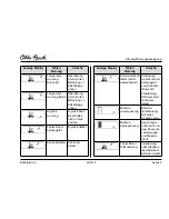
Страница 94: ...03 2010 B500 B500 S Page 94 Safety 2 9 Warning Symbols and Type Plates Fig 1 Signage on the B500 B500 S...
Страница 154: ...03 2010 B500 B500 S Page 154 Disposal...

