background image

03/2010

B500 | B500-S

Page 142

Options

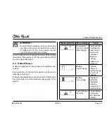
DAnGEr !

The four-way chest strap kit helps to addition-

ally  stabilise  the  person  sitting  in  the  power 

wheelchair. The four-way chest strap kit must 

never be used as part of a restraint system for 

transportation of the person in motor vehicles 

for the disabled.

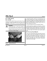
To close the four-way chest strap kit, connect all parts of 

the belt buckle. The belt buckle must snap in place audi-

bly. Then, verify that the belt has locked by trying to pull-

ing it apart. The four-way chest strap kit should not be 

too tight on the body. Objects caught under the belt can 

cause painful pressure sores. 
To increase the length of the belt, turn the buckle by 90° 

and pull. To reduce the length of the belt, pull the over-

hanging belt end.

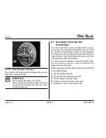
8.9.3 Headrest Mounting Kit (Standard Seat)

Another option is to have the power wheelchair equipped 

with a headrest. For this purpose, the mounting kit 

showed in figure 38 is required.

fig. 38 

Headrest mounting kit

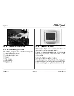
8.9.4 rear Bumper

Equipping the B500 power wheelchair with a bumper is 

also an option (fig. 39).

Содержание B 500-S

Страница 1: ...Bedienungsanleitung Instructions for Use Packma Folding size Detail Felge B500 S Rim B500 S Elektrische Sitzkantelung Electric seat tilt B500 B500 S...

Страница 2: ......

Страница 3: ...nutzer 15 2 8 Sicherheitsfunktionen 16 2 9 Warn und Typenschilder 17 3 Technische Daten 20 4 Produktbeschreibung 22 5 Transport und Lagerung 23 6 Lieferung und Inbetriebnahme 24 6 1 Lieferung 24 6 2 I...

Страница 4: ...u raste 59 8 5 2 Elektrisch einstellbare Fu rasten 60 8 6 Bedienpulthalter 60 8 6 1 H henverstellbarer Bedienpulthalter 60 8 6 2 Wegschwenkbarer Bedienpulthalter 61 8 7 Externer Kilometerz hler 61 8 8...

Страница 5: ...Abb 20 Elektrische Sitzkantelung 50 Abb 21 Mechanische R ckenwinkelverstellung 50 Abb 22 Elektrische R ckenwinkelverstellung 51 Abb 23 Ausgefahrene Hubvorrichtung B500 S 54 Abb 24 Schneckensymbol zur...

Страница 6: ...ist deshalb vor Gebrauch des Elektrorollstuhls vom Bediener und den Begleitpersonen sorgf ltig zu lesen Damit wird die volle Nutzung der Leistungsf higkeit des Elektrorollstuhls gesichert Die Bedienun...

Страница 7: ...zu sch tzen und den B500 sicher und fehler frei zu bedienen Die Betriebssicherheit des B500 ist nur bei bestim mungsgem er Verwendung entsprechend den Anga ben in dieser Bedienungsanleitung gew hrlei...

Страница 8: ...e und besch digte Teile sowie f r den neuen Anwender unpassende ungeeignete Kompo nenten sind auszutauschen Ein Serviceplan f r jedes Modell Detailinformationen sowie die ben tigten Werkzeuge sind der...

Страница 9: ...best tigt 2 2 CE Konformit t Das Produkt erf llt die Anforderungen der Richtlinie 93 42 EWG f r Medizinprodukte Aufgrund der Klassi fizierungskriterien f r Medizinprodukte nach Anhang IX der Richtlin...

Страница 10: ...Sie sich in diesem Fall unverz glich an Ihren autorisierten Fachh ndler 2 4 Sicherheitsanforderungen f r Transport Lagerung und Montage r r F r den Transport d rfen nur ausreichend dimen sionierte He...

Страница 11: ...n Zustand des Elektrorollstuhls einschlie lich der Sicherheitsfunk tionen zu berzeugen Der Elektrorollstuhl darf nur betrieben werden wenn alle Sicherheitsfunktionen wie z B die selbstt tigen Bremsen...

Страница 12: ...et werden r r DieAktuatorenderSitzfunktionensindnichtf rDauer betrieb sondern nur f r eine kurzzeitig begrenzte Belas tung ausgelegt 10 Anstrengung 90 Pause Als Richtwert gilt Bei max Zuladung sind na...

Страница 13: ...Begleitperson d rfen nicht in den Gefahrenbereich fassen r r DieSteuerungdesElektrorollstuhlsistnachSchutzart IP 54 gesch tzt und kann dementsprechend bei schlechten Wetterbedingungen z B Regen genutz...

Страница 14: ...nn durch Entriegeln der Bremse in die Schiebfunk tion umgeschaltet werden Danach muss auf jeden Fall ein Fachh ndler aufgesucht werden r r Gibt die Steuerung beim Bet tigen des Brems hebels kein Fehle...

Страница 15: ...tfernen r r Die Reinigung des Elektrorollstuhls darf auf keinen Fall mit einem Wasserstrahl oder Hochdruckreiniger durchgef hrt werden Direkter Wasserkontakt mit Elektronik Motor und Batterie ist unbe...

Страница 16: ...ktoren zu tragen 2 8 Sicherheitsfunktionen Im Gefahrenfall kann der B500 ber die Ein und Aus schalttaste jederzeit abgeschaltet werden Beim Bet ti gen der Taste wird der Elektrorollstuhl sofort gebrem...

Страница 17: ...03 2010 B500 B500 S Seite 17 Sicherheit 2 9 Warn und Typenschilder Abb 1 Beschilderung am B500 B500 S...

Страница 18: ...l Technische Daten E Zul ssige Achslast vorn hinten F Zul ssiges Gesamtgewicht G Symbol f r die getrennte Sammlung von Elektro und Elektronikger ten Komponenten des Elektrorollstuhls und die Batterien...

Страница 19: ...19 Sicherheit Label Etikett Bedeutung A B A Elektrischer Fahrbetrieb Motorbremse verriegeln B Manueller Schiebebetrieb Motorbremse entriegeln Quetschgefahr Nicht in den Gefahrenbereich fassen Tab 1 Be...

Страница 20: ...amth he 103 cm Gesamtl nge 108 cm Leergewicht 95 kg max Zuladung 140 kg Patientengewicht Wendekreis 155 cm Reifengr e Lenkrad Antriebsrad 9 10 14 Luftdruck siehe Reifenmantel Elektrische Anlage Betrie...

Страница 21: ...tzanschluss 230 V 10 6 Netzfrequenz 50 Hz 4 Schutzklasse 1 Schutzleiter Ladeanschluss 24 V DC Nennladestrom 9 A Restwelligkeit 1 Ladekennlinie IUU mit Erhaltungsladestufe computergesteuert Ladeger t S...

Страница 22: ...reundlichkeit durch einfache und bersicht liche Zug nglichkeit zu allen Baugruppen r r Individuelle Anpassungsm glichkeiten durch Opti onen und Sonderbau ber modulare Komponenten Fahrgestell Sitzsyste...

Страница 23: ...zum Transport im Behindertentrans portkraftwagen BTW Bestellnummer 646D158 gefahr Verletzungsgefahr durch ungen gende Arretie rung Sichern sie den Elektrorollstuhl beim Transport in einem anderen Fah...

Страница 24: ...lagert werden F r Transport und Lagerung sind Umgebungstempera turen von 40 C bis 65 C einzuhalten 6 Lieferung und Inbetriebnahme 6 1 Lieferung Zum Lieferumfang geh ren r r Angepasster Elektrorollstuh...

Страница 25: ...5 Lieferung und Inbetriebnahme 1 2 3 4 5 6 7 8 Abb 3 Hauptkomponenten B500 B500 S 1 R ckenlehne 2 Joystick und Steuerung 3 Armauflage Seitenteil 4 Sitzkissen 5 Bremsentriegelung 6 Fu auflage 7 Motor m...

Страница 26: ...s die 80 A Schmelzsicherung in den daf r vor gesehenen Sicherungshalter am hinteren Ende der Batterie wanne siehe Abb 4 gesteckt werden Entnehmen Sie dazu die Sicherung aus der mitgeliefer ten Schutzh...

Страница 27: ...ellt und d rfen nur vom Fachh nd ler ge ndert werden Vom Benutzer k nnen angepasst werden R ckenwinkel Armauflagenh he Position der Armauflage Unterschenkell nge Die Fu rasten und die Seitenteile k nn...

Страница 28: ...ils das Bedienpult abgesteckt werden Kap 7 1 3 Die Fl gelschrauben befinden sich am unteren Ende der Armauflagenhalter siehe Pfeil Abb 6 Abb 6 Seitenteil herausnehmen Nach Einsetzen des Seitenteils is...

Страница 29: ...auf der rechten Seite installiert Je nach Bedarf kann es auch an der linken Armauflage befestigt werden Das Bedienpult ist durch ein Federblech mit der Schiene verbunden die unter der Armauflage befes...

Страница 30: ...en und nehmen Sie diese ab Anbau 1 H ngen Sie die Fu raste von oben in die Halterung ein und schwenken Sie diese nach vorn bis die Arretierung der Fu raste einrastet 2 H ngen Sie das Wadenband an der...

Страница 31: ...ann jeder Benutzer individuell in der f r ihn am besten geeigneten Art und Weise vornehmen gefahr Verletzungsgefahr durch Wegrollen des Elektro rollstuhls Zum Ein und Aussteigen muss die Steuerung des...

Страница 32: ...wie in Kap 7 1 2 beschrieben ab Ggf demontieren Sie die Fu raste siehe Kap 7 1 4 Der Benutzer kann jetzt von der Seite auf die Sitzfl che rutschen Das Verwenden eines Rutschbrettes erleichtert diesen...

Страница 33: ...St rungen anderer Ger te f hren k nnen Wenn keine Funktion ben tigt wird ist die Steuerung daher stets auszuschalten 7 3 1 Bedienpult Die Steuerung des Elektrorollstuhls erfolgt ber das Bedien pult Da...

Страница 34: ...rt nt solange die Taste f r die Hupe bet tigt wird Warnblinken Durch Bet tigen der Warnblinktaste werden alle vier Blinker aktiviert Licht Die Front und Heckbeleuchtung wird durch Bet tigen der Lichtt...

Страница 35: ...tigen Bremsen m ssen betriebsbe reit und funktionst chtig sein GEFAHR Unfallgefahr durch zu geringen oder zu hohen Reifenluftdruck Vor jeder Benutzung muss der Elektrorollstuhl auf ausreichende Profil...

Страница 36: ...efahren von Steigungen und Gef llestrecken bis max 17 zugelassen Stei gungen und Gef lle ber diesem Prozentsatz d rfen nicht befahren werden Um eine sichere Bergabfahrt zu gew hrleisten ist die Fahrge...

Страница 37: ...Verz gerungswerte vom Service personal auf die individuellen Benutzerw nsche ein gestellt werden 7 3 4 Batterieanzeige Die Batterieanzeige am LCD Display ist in 7 Segmente unterteilt und zeigt die akt...

Страница 38: ...itz funktionen gleichzeitig ausgestattet wird Werden die elektrischen Fu st tzen getrennt angesteuert gelten sie als zwei unabh ngige elektrische Sitzfunktionen Lassen sich die elektrischen Fu st tzen...

Страница 39: ...pstabilit t reduziert Kriech gang Dies wird am Bedienpult durch ein Schnecken symbol im LCD Anzeigefeld angezeigt siehe Abb 24 Elektrische Fu st tzen Bei Auslenken des Joysticks nach vorn oder hinten...

Страница 40: ...vordere Endlage dr cken bis ein Piepton ert nt 3 Joystick in die hintere Endlage dr cken bis ein Piepton ert nt 4 Joystick loslassen 5 Erneuter Piepton best tigt die erfolgreiche Deakti vierung der W...

Страница 41: ...GEFAHR Das Entriegeln der Bremse kann zu unkontrol liertem Wegrollen des Elektrorollstuhls f hren Beim Abstellen des Elektrorollstuhls ist daher darauf zu achten dass die Bremse verriegelt ist Bremse...

Страница 42: ...6 Zur Aktivierung der Fahrfunktion m ssen Sie die Steuerung aus und wieder einschalten Abb 16 Bremse verriegeln 7 5 Batterien Der Elektrorollstuhl B500 ist in der Standardausf hrung mit zwei 12 V Nass...

Страница 43: ...fernt werden Dazu ist die Klettverbindung zwischen R ckenlehne und Sitzfl che zu l sen und die Sitzfl che abzu nehmen 2 Schnappverschluss des Haltegurtes an der Bat teriewanne l sen siehe Abb 17 und d...

Страница 44: ...Sorgen Sie in geschlossenen R umen f r aus reichende Bel ftung Rauchen Sie nicht und entfachen Sie kein Feuer Vermeiden Sie unbedingt Funkenbildung Verdecken Sie nicht die L ftungsschlitze in der Verk...

Страница 45: ...bei l ngeren Standzeiten die Sicherung zu ziehen r r Die Batterien sollten nie komplett entladen werden Tiefentladung r r Die Steuerung des Elektrorollstuhls ist w hrend des Ladevorganges abzuschalte...

Страница 46: ...rw rmungdesGer tes zu verhindern r r Der Aufstellort muss trocken und gut bel ftet sein Das Eindringen von Staub und Schmutz vermeiden Dadurch kann die Funktion des Ladeger tes beein tr chtigt werden...

Страница 47: ...Netz vorhanden 8 Optionen Achtung Es d rfen nur Original Optionen vom Herstel ler verwendet werden Die optionalen Kompo nenten d rfen nur wie hier beschrieben mon tiert werden Nichtbeachtung f hrt zum...

Страница 48: ...d Klemmgefahr der Finger Beim Kippen des Sitzes darf nicht mit dem Finger in den Gefahrenbereich zwischen Rahmen und Sitz gefasst werden Es d rfen sich keine st ren den Objekte oder Hindernisse im Kip...

Страница 49: ...es Absenken In geneigter Sitzposition kann sich bei Bet ti gen des Ausl sehebels der Sitz ruckartig absenken Um den Sitz nach hinten zu kippen siehe Abb 19 r r Ausl sehebel an der Armauflage bet tigen...

Страница 50: ...er mechanischen R ckenwinkelverstellung ausger stet werden Um die R ckenlehne zu verstellen siehe Abb 21 r r Ausl sehebel an Armauflage bet tigen Blockierung der Gasdruckfeder aufgehoben r r R ckenleh...

Страница 51: ...ippen des Elek trorollstuhls Der Elektrorollstuhl kann bei aus gefahrener Hubvorrichtung umkippen und der Bediener herausfallen Deshalb folgende Sicherheitsma nahmen unbedingt einhalten Mit ausgefahre...

Страница 52: ...sonen darauf hin dass sich im Bereich zwischen Sitzrahmen und Rollstuhlrahmen konstruktionsbedingte Quetschkanten befinden Bediener und Begleitperson d rfen bei elektrischen Sitzver stell und Hubfunkt...

Страница 53: ...Hubvorrichtung ist nicht f r den Dauerbe trieb sondern nur f r eine kurzzeitig begrenzte Belastung ausgelegt 10 Anstrengung 90 Pause Bei einer Betriebsdauer von 1 Stunde kann die Hubfunktion max 6 Mi...

Страница 54: ...llst hle mit R ckenwinkelverstellung F r die Einstellung des Packma es ist folgendes an der R ckenwinkelverstellung vorzunehmen r r Querbolzen am unteren Ende der Gasdruckfeder entriegeln Hebel nach o...

Страница 55: ...legen r r Bolzen verriegeln Hebel nach unten dr cken Ver riegelung rastet am Bolzen ein siehe Abb 25 achtung Bolzen und Verriegelung der R ckenwinkelver stellung auf festen Sitz berpr fen 8 2 Beleucht...

Страница 56: ...hen Sie folgenderma en vor r r Scheibe durch leichten Druck auf den schwarzen RasthebelamunterenEndedesBeleuchtungsk rpers nach vorn klappen siehe Abb 27 Pos 1 Abb 27 Wechsel der Frontbeleuchtung 1 Ra...

Страница 57: ...olgenderma en vor siehe Abb 29 r r Scheibe abschrauben r r Die Gl hlampe der Heckbeleuchtung sind rechts und links berfederndeLamellenbefestigt Durchleichten Druck nach rechts die Lampe auf der linken...

Страница 58: ...ung verf gt der B500 ber ein Batterieschubfach Batterieschubfach ffnen r r Entriegelungsbolzennachobenziehen sieheAbb 30 r r Schublade durch leichten Zug nach hinten heraus rollen r r Schnappverschlus...

Страница 59: ...tion drehen Lenk radgabel entriegelt und wieder frei drehbar r r Hebel rastet in der Mitte des Vorderrahmens in ent riegelter Position ein siehe Abb 31 rechtes Bild 8 5 Hochschwenkbare Fu rasten 8 5 1...

Страница 60: ...Elektrorollstuhl elektrisch einstellbare Fu st tzen ange bracht werden Abb 33 Im Modus Zusatzfunktion der Steuerung k nnen beide Fu st tzen je nach bestellter Version einzeln oder gleichzeitig bet tig...

Страница 61: ...alter ist bis zur Armlehne drehbar r r Bedienpulthalter mit etwas Druck zur Seite dr cken das Drehelement wird entriegelt r r Bedienpulthalter seitlich wegschwenken r r Beim Zur ckdrehen in die Urspru...

Страница 62: ...s 2 Sekun den dr cken Am Display blinken 12 und 24 im Wech sel Durch Tastendruck bei 24 wird die 24 Stunden Anzeige und bei 12 die 12 Stunden Anzeige aktiviert Danach k nnen Stunden und Minuten einges...

Страница 63: ...n der Ausgangsstellung wieder ein Dieses sichere Einras ten ist nach jedem Entriegeln der R ckenlehne zu ber p fen Bei der R ckenlehne Recaro LT kann die Seitenf hrung im Lendenbereich durch Drehen de...

Страница 64: ...n Haltebuchsen sitzen Die vorderen Arretierungsbolzen m ssen bis zum Schl sselring eingerastet sein r r Hintere Kante des Recaro Sitzes am Ende des Sitz rahmens aufsetzen r r Sitz nach vorn schieben b...

Страница 65: ...ht zu straff zwischen Beckengurt und Oberschenkel plaziert werden Das Gurtschloss liegt mittig vor dem K rper Die Schultergurte sollten beidseitig gleich nicht zu straff auf dem Brustkorb liegen gefah...

Страница 66: ...hinten 8 9 5 Weitere Optionen r r Kantensteighilfe Die Kantensteighilfe dient zur berwindung von Kan ten und Stufen mit einer Maximalh he von 10 cm r r Pannensichere Bereifung Vollgummireifen r r Con...

Страница 67: ...gung Probleme auf oder k nnen die auftretenden St rungen mit den hier beschriebenen Ma nahmen nicht vollst ndig behoben werden wenden Sie sich bitte an Ihren Fachh ndler Die Anzeige erfolgt ber das Di...

Страница 68: ...nach Problemfall der Rollstuhl aus einer Gefahrenzone z B im Stra enverkehr gefahren werden Ist die Fahrbe reitschaft auch nach dem Einschalten nicht vor handen kann durch Entriegelung der Bremse sieh...

Страница 69: ...osition Fehler Hand bedienger t Joystick defekt Kontrollerfehler Kontroller defekt Anzeige Display Fehler Warnung Ursache Kommunikations fehler blinkt abwechselnd Verbindung zwischen Hand bedienger t...

Страница 70: ...stellung von Ersatzteilen kann bei Otto Bock ein Ersatzteilkatalog angefordert werden Es d rfen nur Ersatz und Verschlei teile von Otto Bock verwendet werden Nicht beachten f hrt zum Verlust von Gew h...

Страница 71: ...ezogen X X X Sitzbefestigung Befestigungsschrauben auf festen Sitz pr fen Sitzverriegelung bei Recaro Sitz pr fen X X Fu raste Rastung auf Funktion und festen Sitz pr fen Fu auflage auf Besch digung p...

Страница 72: ...X Bremse Bremshebel bei eingeschalteter Steuerung bet tigen X Bremsfunktion bei eingeriegelter Bremse aktiv X Hubsitz Sichtpr fung aller beweglichen Teile insbesondere der Verkabelung auf Besch digun...

Страница 73: ...ung wechseln Die 80 A Schmelzsicherung befindet sich in einem Siche rungshalter am hinteren Ende der Batteriewanne siehe Abb 40 ffnen Sie die Kappe des Sicherungshalters und tau schen Sie die Sicherun...

Страница 74: ...lge alle Innensechs kantschrauben l sen und die zweigeteilte Felge auseinander ziehen Der defekte Schlauch ist jetzt frei zug nglich und kann gewechselt werden r r Achsschraube zum Ausbau des Vorderra...

Страница 75: ...f keinen Fall mit Wasserstrahl oder Hoch druckreiniger durchf hren Der Elektrorollstuhl muss in regelm igen Abst nden abh ngig vom Einsatz und Verschmutzungsgrad gerei nigt werden Die Komponenten Bedi...

Страница 76: ...mmen 12 Garantiebedingungen der Otto Bock Mobility Solutions GmbH 1 Gegenstand der Garantie 1 1 Diese Garantie gilt f r Rollst hle 1 2 Die Garantie umfasst Anspr che des Sanit ts hauses Dienstleisters...

Страница 77: ...dizin produkte mit CE Kennzeichen verwendet werden und dabei eine Verwendung entspre chend der diesen Medizinprodukten vorgege benen Zweckbestimmung erfolgt 3 5 Ver nderungen an einem Rollstuhl nicht...

Страница 78: ...beruht 5 Haftung F r die Ausf hrung der Leistungen aufgrund dieser Ga rantie haftet die Otto Bock Mobility Solutions GmbH bei Verletzung nicht wesentlicher Ver pflich tungen nur f r leichte Fahrl ssi...

Страница 79: ...03 2010 B500 B500 S Seite 79 Garantiebedingungen der Otto Bock Mobility Solutions GmbH...

Страница 80: ...Instructions for Use Instructions for Use 03 2010 B500 B500 S Seite 80...

Страница 81: ...ates 94 3 Technical Data 97 4 Product Description 99 5 Transport and Storage 100 6 Delivery and Putting into Operation 101 6 1 Delivery 101 6 2 Putting into Operation 103 7 Operation 104 7 1 Adjustmen...

Страница 82: ...ically Elevating Footrest 136 8 5 2 Electrically Adjustable Footrests 136 8 6 Control Panel Holders 137 8 6 1 Height Adjustable Control Panel Holder 137 8 6 2 Swing away Control Panel Holder 137 8 7 E...

Страница 83: ...20 Electric seat tilt adjustment 127 Fig 21 Mechanical back angle adjustment 127 Fig 22 Electric back angle adjustment 128 Fig 23 Lift seat in raised position B500 S 130 Fig 24 Snail symbol indicating...

Страница 84: ...cially the section on Safety before using the power wheelchair This will ensure the complete utilisation of all the features of the power wheelchair The instructions for use have been prepared on the...

Страница 85: ...s used properly in accordance with the information contained in these instructions for use The user is ulti mately responsible for accident free operation 1 3 Liability The manufacturer s warranty app...

Страница 86: ...or are unsuitable for the new user must be replaced The service manual includes a service plan for each model detailed information and a list of the required tools 1 5 Service note Service and repair...

Страница 87: ...e meets the requirements of the 93 42 EEC guidelines for medical devices This device has been classified as a class I device according to the classifica tion criteria outlined in appendix IX of the gu...

Страница 88: ...r immediately 2 4 Safety Requirements for Transport Storage and Assembly r r Only sufficiently strong hoisting devices may be used for transport r r Thepowerwheelchairmustbesecuredinaccordance withthe...

Страница 89: ...as the automatic brakes are functional Inoperable brakes can lead to severe accidents with fatal injuries r r Thepowerwheelchairmustbeinspectedforfunctional reliability and driving safety at least on...

Страница 90: ...cialist dealer immediately The power wheelchair may only be used with the seat in its lowest position until the problem is corrected r r The power wheelchair must be visually checked every time before...

Страница 91: ...u do not need them r r The tyres of the power wheelchair contain chemical substances that can react to other chemical sub stances such as cleaning agents acids etc r r Direct sunlight UV light causes...

Страница 92: ...covered r r For power wheelchairs featuring a battery drawer Whenclosingthebatterydrawer thereleaseboltmust engage in the recess provided for this purpose The release bolt must be easy to see and tou...

Страница 93: ...chair may not be operated in cases of exhaustion or under the influence of alcohol or drugs The user may not have any mental restrictions which can temporarily or permanently restrict attentiveness an...

Страница 94: ...03 2010 B500 B500 S Page 94 Safety 2 9 Warning Symbols and Type Plates Fig 1 Signage on the B500 B500 S...

Страница 95: ...sible axle load front rear F Permissible total weight G Symbol for separate collection of electric and electronic devices Components of the power wheelchair and the batteries must not be disposed of l...

Страница 96: ...Page 96 Safety Label Type Plate Explanation A B A Electric driving operation lock motor brake B Manual pushing mode unlock motor brake Risk of pinching Do not reach into the danger area Table 1 Signag...

Страница 97: ...m Weight empty 95 kg Maximum load capacity 140 kg patient weight Turning radius 155 cm Tyre size Caster Drive wheel 9 10 14 Air pressure printed on the sidewall of the tyre Electrical Installation Ope...

Страница 98: ...ements 230 V 10 6 Mains frequency 50 Hz 4 Protective system 1 protective conductor Charging connection 24 V DC Nominal charging current 9 A Battery charger Residual ripple 1 Characteristic curve IUU w...

Страница 99: ...ures of the power wheelchair include r r Easy servicing due to good and clear accessibility of all component groups r r Customisationthroughoptionsandspecialfabrication with modular components chassis...

Страница 100: ...Seating Shell or Buggy Stroller for Transportation in Motor Vehicles order no 646D158 danger Risk of injury as a result of not engaging the locks sufficiently Secure the power wheelchair during transp...

Страница 101: ...st be stored in a dry place For transport and storage an ambient temperature range from 40 C to 65 C must be observed 6 Delivery and Putting into Operation 6 1 Delivery Delivery includes r r Adapted p...

Страница 102: ...livery and Putting into Operation 1 2 3 4 5 6 7 8 Fig 3 Main components of the B500 B500 S 1 Backrest 2 Joystick and control unit 3 Armrest side panel 4 Seat cushion 5 Brake release 6 Footrest 7 Motor...

Страница 103: ...s compo nents must be checked Before the power wheelchair can be switched on the 80 A fuse must be inserted into the fuse holder at the rear end of the battery case see fig 4 To do so remove the fuse...

Страница 104: ...t in accordance with the indications on the customer order form and may only be changed by the specialist dealer The following items can be adapted by the user Back angle Armrest height Armrest positi...

Страница 105: ...d before taking out the side panel section 7 1 3 The thumb screws are located at the lower end of the armrest holders see arrow in fig 6 Fig 6 Removing the side panel After remounting the side panel d...

Страница 106: ...guration has the control panel mounted on the right side If required it can also be mounted on the left armrest Spring sheet metal connects the control panel to the rail which is attached below the ar...

Страница 107: ...otrest up to remove it Reassembly 1 Reinsert the footrest from above by placing it in the holding device and swinging it forward until the footrest lock engages 2 Reattach the calf band to the holding...

Страница 108: ...the wheelchair can be done by the user individually in a way that suits him or her best danger Risk of injury if the power wheelchair starts rolling When getting into or out of the power wheel chair t...

Страница 109: ...l off the control panel Remove the side panel as described in section 7 1 2 If necessary remove the footrest see section 7 1 4 The user can then slide onto the wheelchair s seat from the side Use of a...

Страница 110: ...erence with other devices Therefore switch off the controls whenever you do not need them 7 3 1 Control Panel The control panel is used to control the power wheelchair The control panel consists of a...

Страница 111: ...ressed Warning Flasher Pressing the warning flasher button activates all four direction indicators Light The front and rear lights are activated and deactivated by pressing the light button Direction...

Страница 112: ...or operation and func tional DANGER Risk of accident as a result of insufficient or excessive tyre pressure The power wheelchair must be visually checked every time before it is used to make sure that...

Страница 113: ...lopes of no more than 17 You are not allowed to drive on inclines or slopes steeper than this To ensure safe downhill driving the driving speed must be reduced in accordance with the degree of incline...

Страница 114: ...ator The battery indicator on the LCD display consists of 7 segments and shows the remaining battery capacity NOTE Immediately after switching the power wheel chair on the battery indicator shows the...

Страница 115: ...maximum of two electric seat functions at a time Should the electric footrests be controlled in dividually they operate as two independent electric seat functions If the electric footrests left right...

Страница 116: ...reep speed because the power wheelchair is less tip resistant This is indicated by a snail symbol on the control panel LCD monitor see Figure 24 Electric footrests Deflecting the joystick ahead or bac...

Страница 117: ...ess the On Off button to turn on the control 2 Move the joystick into the front end position until you hear a beep 3 Move the joystick into the rear end position until you hear a beep 4 Release the jo...

Страница 118: ...ing of the power wheelchair Therefore make sure that the brake is engaged after parking the power wheelchair Releasing the Brake Fig 15 For reasons of safety you must first pull up the brake release b...

Страница 119: ...e the driving function switch off the wheelchair controls and then switch them on again Fig 16 Locking the brake 7 5 Batteries The standard version of the B500 power wheelchair includes two low mainte...

Страница 120: ...unting removing the batteries For this purpose undo the hook and loop connection between the backrest and seat bottom and remove the seat bottom 2 Undo the snap lock on the safety strap for the batter...

Страница 121: ...when charging the batteries in closed rooms Smoking and fire are not permitted Sparks must be avoided Do not cover the vent slots in the housing ATTENTION Battery damage Driving over a longer period...

Страница 122: ...Wealsorecommendremovingthefuse when the power wheelchair is not going to be used for an extended period of time r r Total discharge of the batteries should be avoided r r When the batteries are chargi...

Страница 123: ...rmer than it already is r r The place where the battery charger will be used must be dry and well ventilated Avoid letting dust and dirt enter and affect the function of the battery charger r r To cle...

Страница 124: ...here is no power supply 8 Options Attention Only original options provided by the manufac turer may be used The optional components may be mounted only as described here Fail ure to comply will render...

Страница 125: ...each into the danger zone between the frame and the seat when tilting the seat There must not be any interfering objects or obstacles in the tilting area danger Overloading the actuators can result in...

Страница 126: ...fig 19 r r Use the release lever on the armrest to unblock the gas compression spring r r Tilt the seat to the desired inclination r r Let go of the release lever to again block the gas compression sp...

Страница 127: ...e desired position r r Let go of the release lever to again block the gas compression spring Fig 21 Mechanical back angle adjustment 8 1 4 Electric Back Angle Adjustment The backrest of the standard s...

Страница 128: ...elt if possible r r Only use the lift seat function on level sur faces r r Do not change the mounting position of the lift seat mechanism or the lift seat r r For lift seat retrofit or conversion obse...

Страница 129: ...osition and when activating the lift seat function Danger Risk of tipping in case of additional use of the seat tilt function The seat tilt function must be set to the horizontal position when driving...

Страница 130: ...h the lift seat function the seat can be raised by up to 40 cm using a motor Figure 23 It is controlled by the joystick in additional function mode The drive function remains available even when the l...

Страница 131: ...seearrow in fig 25 r r Remove the bolt from the holding device r r Remove the side panels and fold down the back part onto the seat bottom Fig 25 Cross bolt locked in the holding device 1 Cross bolt...

Страница 132: ...rear lights are attached to the wheelchair frame Button 9 on the control panel see fig 13 is used to switch the lights on Symbol 16 on the LCD display see fig 14 indicates that the lights are turned o...

Страница 133: ...cator Insertasmallscrew driver into the recess of the direction indicator housing and flip down the pane of the direction indicator see fig 27 item 2 r r Remove the pane r r Slightly rotate the bulb t...

Страница 134: ...pring damping element on each of the two casters increases driving comfort and provides bet ter adherence to the ground especially when driving on uneven terrain This can be improved even more by also...

Страница 135: ...the front frame to the side thus allowing it to jump out of its normal mid position r r A bolt is released from the frame and engages in the front caster fork as soon as the straight forward posi tio...

Страница 136: ...tinuous use but only for short term lim ited operation General recommendation At maximum load capacity 10 seconds of opera tion should be followed by 90 seconds of idle time The electric seat function...

Страница 137: ...ment screw Fig 34 Height adjustment of control panel holder 8 6 2 Swing away Control Panel Holder To allow the user to drive the power wheelchair closer to an object or under the edge of a table the c...

Страница 138: ...l clock Fig 36 External mileage counter Whenever the display shows km h or m h in the upper left corner the speedometer is activated Pressing the yellow button lets you see the trip mileage total mile...

Страница 139: ...ize and can be set in the same way the clock is For a wheel size of 14 inches Conversion from inches to cm 14 x 25 4 355 6 mm C d x p 355 6 mm x 3 1416 1 117 mm wheel circumference to be set 8 8 Recar...

Страница 140: ...needed to remove the headrest The pressure points must be detected under the cover by feel and be pressed simultaneously Now the second person can pull the headrest out upwards Removing the Recaro Sea...

Страница 141: ...ed by trying to pulling it apart The lap belt should not be too tight on the body Objects caught under the belt can cause painful pressure sores To open the lap belt press the red release buttons The...

Страница 142: ...rify that the belt has locked by trying to pull ing it apart The four way chest strap kit should not be too tight on the body Objects caught under the belt can cause painful pressure sores To increase...

Страница 143: ...eating shells are also available r r Armrest accessories Special adapter for the armrests in our wheelchair accessories catalogue r r Control for attendant External joystick on the backrest r r Joysti...

Страница 144: ...an be used for determining future service and maintenance intervals for example 9 1 Warning A warning indicates a status or malfunction of one or sev eral individual components of the power wheelchair...

Страница 145: ...m com ponent After elimination of the fault the system will be re acti vated by re starting it A failure represents the most serious kind of fault possi ble and results in an immediate emergency stop...

Страница 146: ...position when switch ing on Fault with hand control device Defective joystick Controller fault Defective controller Fault with back adjust ment motor Faulty cabling or plug con tact defective actuator...

Страница 147: ...ender the warranty null and void NOTE Should you encounter problems during main tenance contact your authorised dealer The power wheelchair is to be checked and serv iced once a year by an authorised...

Страница 148: ...reely and without axial run out Fastening nut tightened X X X Seat attachment Check if mounting screws are securely in place Check seat lock of Recaro seat X X Footrest Check ratchet mechanism for fun...

Страница 149: ...Check plug connections Prior to every ride X X Brake Use the brake lever with the controls turned on X Brake function active with engaged brake X Lift seat Visual inspection of all moving components e...

Страница 150: ...blem must be eliminated immediately by a specialist dealer 10 2 Changing the Fuse The 80 A fuse is located in a fuse holder at the rear end of the battery case see fig 40 Open the cap of the safety ho...

Страница 151: ...loosen all Allen head screws on the inner side of the rim and pull apart the two piece rim The defective inner tube is now freely accessible and can be replaced r r To dismount the front wheel loosen...

Страница 152: ...ver use a water jet or high pressure cleaning apparatus for cleaning the power wheelchair The power wheelchair must be cleaned regularly depend ing on the amount of use and the degree of soiling Use a...

Страница 153: ...es of the power wheelchair contain a toxic acid They must not be disposed of like regular domestic waste and the battery acid must not get into the sewage water system or earth You must observe the in...

Страница 154: ...03 2010 B500 B500 S Page 154 Disposal...

Страница 155: ...ikon Tel 41 41 4556171 Fax 41 41 4556170 suisse ottobock com Otto Bock Healthcare plc GB Egham Surrey TW20 0LD Tel 44 1784 744900 Fax 44 1784 744901 bockuk ottobock com Otto Bock france Snc F 91941 Le...

Страница 156: ...een certi ed by the German Society for the Certi cation of Quality Assurance Systems DQS in accordance with DIN EN ISO 13 485 2007 reg no 435514 MP27 management system Hersteller Manufacturer Otto Boc...

Отзывы: