Service work
490E75=0_C
Ottobock | 87
4.13.12 Replacing and adjusting the seat height adjustment sensor
WARNING
Shifted centre of gravity, unstable driving characteristics of the wheelchair
Tipping over of the wheelchair, pinching, crushing, severe injuries of the user
f
Adjust and verify the function of the seat height adjustment sensor after each replacement.
f
Attach the seat height adjustment sensor according to the original installed position so that the driving speed
is reduced when raising the seat, as it was on delivery.
f
After each replacement, verify the stable driving characteristics of the wheelchair on all slopes the wheelchair
is approved for.
f
Prerequisites:
Activate (lock) the brakes on both drive motors.
Move the seat to the lowest seat height (see Page 15).
Switch off the control unit and deactivate the main fuse (see Page 15).
If necessary: Remove the legrests.
f
Tools: Phillips screwdriver size 3; Allen wrench size 3, 4; torque wrench with Allen insert size 3, 4
Removing the seat height adjustment sensor
1) Fold up the seat (see Page 16).
2) Remove the battery cover (see Page 17).
3) Remove the rear cover (see Page 19).
4) If necessary: Fold down the seat (see Page 16).
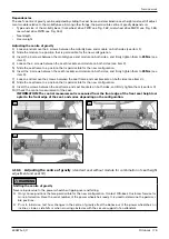
5) Loosen and remove the 4 screws on the module carrier (see Fig. 181, item 1).
6) Carefully lift the module carrier and controller off the frame (see Fig. 181, item 2).
7) INFORMATION: Note the installed position of the cable connections being loosened.
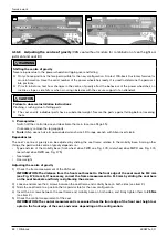
Disconnect the cable for the seat height adjustment sensor (see Fig. 182, item 2).
8) Fold up the seat (see Page 16).
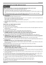
9) Loosen and remove the 2 screws between the bottom of the frame and the sensor bracket (see Fig. 186, item 1).
10) INFORMATION: Take note of the installed position of the cable.
Remove the seat height adjustment sensor with its cable. Remove or open additional cable attachments if neces-
sary (see Fig. 186, item 2).
11) Fold down the seat (see Page 16).
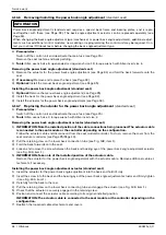
12) If necessary: Remove the seat height adjustment sensor from the sensor bracket (see Fig. 187, item 2). To do
so, loosen and remove the 2 Phillips screws (see Fig. 187/188, item 1).
Installing the seat height adjustment sensor
1) If necessary: OO<>COC@N@<OC@DBCO<?EPNOH@ION@INJMOJOC@N@INJM=M<>F@O{J?JNJxDIN@MO<I?uMHGTODBCO@I
the 2 Phillips screws (see Fig. 187/188, item 1).
2) Fold up the seat (see Page 16).
3) Carefully insert the seat height adjustment sensor and position the cable according to its original installed posi-
tion. Reattach or close the loosened cable attachments (see Fig. 186, item 2).
4) IN@MOOC@¿N>M@RN=@OR@@IOC@=JOOJHJAOC@AM<H@<I?OC@N@INJM=M<>F@O<I?uMHGTODBCO@IOC@HN@@DB{¾ÅÃx
item 1).
5) If necessary: Fold down the seat (see Page 16).
6) Connect the cable for the seat height adjustment sensor according to the original installed position (see Fig. 182,
item 2).
7) Carefully position the module carrier and controller on the frame (see Fig. 181, item 2).
8) IN@MOOC@ÁN>M@RNJAOC@HJ?PG@><MMD@M<I?uMHGTODBCO@IOC@HN@@DB{¾Å¾xDO@H¾{
9) Attach the rear cover (see Page 19).
10) Fold up the seat (see Page 16).
11) Attach the battery cover (see Page 17).
12) Fold down the seat (see Page 16).
13) Verify the functionality of the sensor and adjust it as needed.
Содержание 490E75 Series
Страница 1: ...490E75 0_C Service manual...
Страница 38: ...Service work 490E75 0_C 38 Ottobock 57 58 59 60 61 62 63...
Страница 41: ...Service work 490E75 0_C Ottobock 41 70 71 72 73 74 tt 75 76...
Страница 55: ...Service work 490E75 0_C Ottobock 55 103 104 105 106 107 108 109 110...
Страница 108: ...Service work 490E75 0_C 108 Ottobock 227 228 229 t 230 231 232...
Страница 112: ...Service work 490E75 0_C 112 Ottobock 237 238 239 240 241...
Страница 143: ...R Net wheelchair control 490E75 0_C Ottobock 143 Seat module pin assignment 287...
Страница 161: ...490E75 0_C Ottobock 161...
Страница 162: ...490E75 0_C 162 Ottobock...


