Service work
490E75=0_C
Ottobock | 103
4.15.3 Retrofitting/replacing an elevating side panel (standard seat)
NOTICE
Improper assembly work
Damage to product due to overloading
f
Always insert a supporting profile into the back tube before mounting an elevating side panel. Without inserting
a supporting profile, the load capacity of the standard seat is not sufficient.
f
Always screw the axle (see Fig. 220, item 2) and rotation lock (see Fig. 219, item 1) to the supporting profile.
INFORMATION
Additional or different mounting elements may be required, depending on the seat depth. Note the instructions re-
garding the required spacer washers on Page 106. Only choose positions that are permissible for the respective
components.
f
Prerequisites:
Switch off the control device and deactivate the main fuse (see Page 15).
Remove the seat cushion.
f
Tools: Allen wrench size 5, 6; open-ended wrench size 13; torque wrench with Allen insert size 5, 6
Removing the elevating side panel (standard seat)
1) Remove the seat plate (see Page 74).
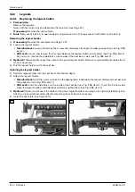
2) Loosen the thumb screw on the arm support holder (see Fig. 252, item 1).
3) Pull the side panel up and out of the arm support holder and set it safely aside. Remove or open additional cable
attachments if necessary.
4) INFORMATION: Note the installed position of the screw connections, spacer washers and accessories.
Never loosen the back support on both sides of the seat frame at the same time.
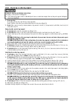
Loosen and remove the screw as well as the starting disc, spacer washer and nut (see Fig. 218, item 2).
zC@M@DNIJNK<>@MR<NC@MRDOCOC@NO<I?<M?N@<ONH<GG{
5) Loosen and remove the arm support holder with the axle (see Fig. 218, item 1).
6) Loosen and remove the rotation lock as well as the spacer washer and nut (see Fig. 219, item 1).
7) INFORMATION: Note the installed position of the screw connections, spacer washers and accessories.
Never loosen the back support on both sides of the seat frame at the same time.
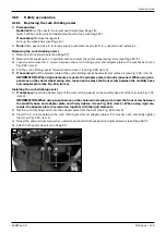
Loosen and remove the rear screws of the seat frame (see Fig. 219, item 2).
8) Remove the adaption.
9) @HJQ@OC@NPKKJMODIBKMJuG@AMJHOC@AM<H@OP=@N@@DB{¿¿½xDO@H¾{J?JNJxM@HJQ@OC@M@<MMD==@?KGPB
from the frame tube.
10) IN@MOOC@M@<MN>M@RNJAOC@N@<OAM<H@<NR@GG<NOC@NK<>@MR<NC@MN<I?IPON<I?uMHGTODBCO@IOC@HN@@
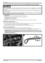
Fig. 221, item 1).
INFORMATION: Additional accessory components, such as a lap belt, may be attached with these
N>M@RNN@@DB{¿¾ÆxDO@HÁ{@NOJM@OC@JMDBDI<GDINO<GG@?KJNDODJI{
11) Seal the frame tube with a ribbed plug (see Fig. 221, item 2).
12) Attach a standard side panel holder (see Page 101).
13) Attach the seat plate (see Page 74).
Installing the elevating side panel (standard seat)
1) Remove the seat plate (see Page 74).
2) Remove the standard side panel holder see Page 101).
3) INFORMATION: Note the installed position of the screw connections, spacer washers and accessories.
Never loosen the back support on both sides of the seat frame at the same time.
Loosen and remove the rear screws of the seat frame (see Fig. 221, item 1).
4) Remove the rear ribbed plug from the frame tube (see Fig. 221, item 2).
5) IN@MOOC@NPKKJMODIBKMJuG@DIOJOC@AM<H@OP=@N@@DB{¿¿½xDO@H¾{
zI?JDIBNJx>C@>FRC@OC@MOC@NPKKJMODIBKMJuG@uONKMJK@MGT<I?><I=@NP=N@LP@IOGT
HJQ@?{?<KOOC@NPKKJMODIBKMJuG@OJOC@AM<H@OP=@DAI@>@NN<MT{
6) KKGTOC@<?<KODJIOJOC@N@<OAM<H@<I?<GDBIOC@NPKKJMODIBKMJuG@NJDODN>@IOM@?M@G<ODQ@OJOC@<?<KO<ODJI{
Содержание 490E75 Series
Страница 1: ...490E75 0_C Service manual...
Страница 38: ...Service work 490E75 0_C 38 Ottobock 57 58 59 60 61 62 63...
Страница 41: ...Service work 490E75 0_C Ottobock 41 70 71 72 73 74 tt 75 76...
Страница 55: ...Service work 490E75 0_C Ottobock 55 103 104 105 106 107 108 109 110...
Страница 108: ...Service work 490E75 0_C 108 Ottobock 227 228 229 t 230 231 232...
Страница 112: ...Service work 490E75 0_C 112 Ottobock 237 238 239 240 241...
Страница 143: ...R Net wheelchair control 490E75 0_C Ottobock 143 Seat module pin assignment 287...
Страница 161: ...490E75 0_C Ottobock 161...
Страница 162: ...490E75 0_C 162 Ottobock...


