Service work
490E75=0_C
28 | Ottobock
f
Prerequisites:
Switch off the control device and deactivate the main fuse (see Page 15).
If necessary: Remove the seat cushion.
f
Tools: Allen wrench size 3, open-end wrench size 8, drill, twist drill Ø 5.2 mm
Removing the single memory function for back support angle adjustment
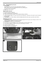
1) Remove the seat module cover (see Page 25 ff.).
2) INFORMATION: Note the installed position of the cable connections being loosened.
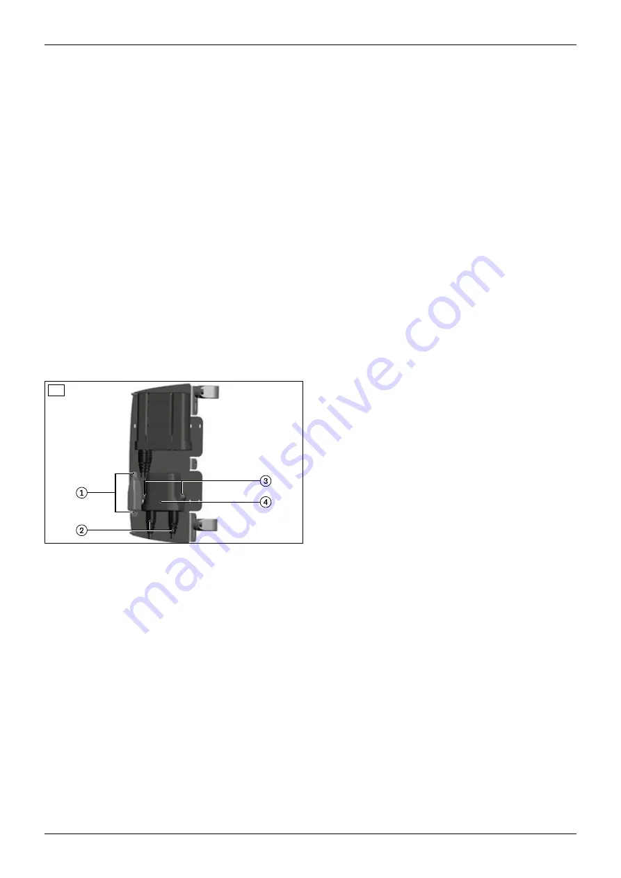
Disconnect the distributor relay cables and remove the distributor relay (see Fig. 33, item 1).
3) Disconnect the cables from the tilt module (see Fig. 33, item 2).
4) Loosen and remove the 2 screws with nuts from the tilt module (see Fig. 33, item 3).
5) Remove the tilt module (see Fig. 33, item 4).
6) If a new memory function is not being installed: Connect the back support angle adjustment actuator to the
seat module. Reconnect other disconnected components to the bus system.
Installing the single memory function for back support angle adjustment
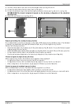
1) Position the tilt module on the module carrier (see Fig. 33, item 4).
2) Insert the 2 tilt module screws with nuts and hand-tighten them (see Fig. 33, item 3).
3) Connect the tilt module to the bus system (see Fig. 33, item 2).
4) Connect the distributor relay to the back support angle adjustment actuator and the seat module (see Fig. 33,
item 1; see Fig. 36).
zC@>C<II@G<NNDBIH@IO?@K@I?NJIOC@M@H<DIDIB>JIuBPM<ODJIJAOC@RC@@G>C<DM
N@@Page¿Æ{
5) Attach the seat module cover (see Page 25 f.).
33
Removing the single memory function for the seat tilt
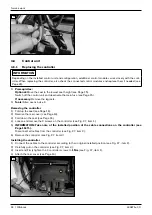
1) Remove the seat module cover (see Page 25 f.).
2) INFORMATION: Note the installed position of the cable connections being loosened.
Disconnect the distributor relay cables and remove the distributor relay (see Fig. 34, item 1).
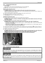
3) Disconnect the tilt module cables underneath the seat plate (see Fig. 35, item 1).
4) Loosen and remove the 2 screws with nuts from the tilt module (see Fig. 35, item 2).
5) Remove the tilt module (see Fig. 35, item 3).
6) If a new memory function is not being installed: Connect the seat tilt actuator to the seat module. Reconnect
other disconnected components to the bus system.
Installing the single memory function for the seat tilt
1) If necessary: Drill 2 holes (
Ø
5.2 mm, spacing 74.0 mm) through the seat plate at the rear (see Fig. 35, item 2).
zC@KJNDODJIJAOC@=JM@N?@K@I?NJIOC@>JIuBPM<ODJIJAOC@RC@@G>C<DM{CJJN@<I
available installation space for the module so that collisions cannot occur.
2) Set the tilt module onto the seat plate from below so that the bus connections face to the rear (see Fig. 35,
item 3).
Содержание 490E75 Series
Страница 1: ...490E75 0_C Service manual...
Страница 38: ...Service work 490E75 0_C 38 Ottobock 57 58 59 60 61 62 63...
Страница 41: ...Service work 490E75 0_C Ottobock 41 70 71 72 73 74 tt 75 76...
Страница 55: ...Service work 490E75 0_C Ottobock 55 103 104 105 106 107 108 109 110...
Страница 108: ...Service work 490E75 0_C 108 Ottobock 227 228 229 t 230 231 232...
Страница 112: ...Service work 490E75 0_C 112 Ottobock 237 238 239 240 241...
Страница 143: ...R Net wheelchair control 490E75 0_C Ottobock 143 Seat module pin assignment 287...
Страница 161: ...490E75 0_C Ottobock 161...
Страница 162: ...490E75 0_C 162 Ottobock...


