20
20
Maintenance Adjustments and Alignments
Caution! Disconnect and lockout power supply before making any adjustments or alignments.
Your saw has been completely assembled, aligned and tested at the factory...then partially disassembled for shipment. Han-
dling during shipment may cause some misalignment and the following information will enable you to correct any cutting
inaccuracy you discover. These adjustments may also be necessary after a period of use. (See preventive maintenance on
page 7 of this manual.)
Important ...
Since one adjustment may affect another it is important to run through the adjustments in the sequence as
follows.
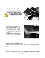
Adjustment of Base to Column Fit
If excessive side motion exists at the end of the arm
while the arm clamp is engaged, adjustment to the base
or bronze gib (C) is generally necessary. To adjust:
1.
Loosen all pinch bolts (A) and set screws (B). Pull
the arm clamp handle forward.
2.
With the motor and yoke in the rearmost position
the elevation effort should be easy. Tighten the
bottom pinch bolt until there is an increase in the
elevation effort. Once elevation becomes snug back
off the bolt 1/4
-
1/2 turn. Repeat this for all the
pinch bolts.
3.
Tighten the gib set screws (B) hard, then back them
off. Run them back up against the gib lightly, then
snug up the locknut.
4.
If the saw is equipped with a column clamp handle
the adjustment should be made so that the clamp
firmly secures the post when pushed back and re-
leased when the handle is pulled forward.
Adjustment of the Arm Clamp
The arm clamp holds the arm tightly on the column
in the desired position for cutting. The arm clamp
handle should be upright when tightened. If it goes
beyond center adjust as follows:
1.
Place motor carriage in the rearmost position.
2.
Loosen the arm clamp set screw (A).
3.
Move arm clamp handle to upright position and
tighten the arm clamp handle bolt (B). Note
this is a left hand threaded bolt.
4.
Tighten the screw.
Adjustment of the Roller head to Arm
Accurate work cannot be done if the roller bearings in the motor carriage are not in proper adjustment. When play develops
between the roller head and the arm the following adjustment is required:
1.
Bring the roller head to the front of the arm and lock in place using the adjustable stop. Move saw to in
-
rip position.
2.
Loosen the sockethead screws holding the arm end cap and rotate the end cap upward to expose bearings.
3.
Clean the tracks thoroughly. Wipe them clean with a solvent,
do not
use kerosene. Use extreme caution as most sol-
vents are toxic and/or flammable.
Do not
grease or oil the tracks.
4.
Loosen the locking set screws (A) two full turns to release the eccentric shafts. (Both are located on the right hand
side.)
Continued on the next page
C
B
A
Содержание 3531-01
Страница 11: ...11 11...


