13
13
SAW ASSEMBLY AND INSTALLATION
…
continued
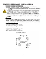
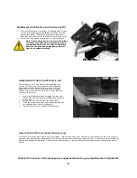
Check Arbor Rotation (3 Phase Only)
Check arbor rotation with arbor nut and arbor collars removed. Open line disconnect to the saw to remove arbor nut and col-
lars, close the line disconnect and start saw. The rotation of the arbor must be clockwise as indicated on the arrow on the
nameplate. If the rotation is counterclockwise, the incoming wires are not properly connected to the switch box. To change the
direction reverse any two of the wires leading to the switch box from the power supply.
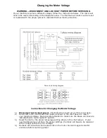
Changing Voltage on dual voltage motors
and Resetting Thermal Protection
Dual voltage motors can be operated on either of the two voltages indicated on the motor
nameplate. The voltage setting from the factory can be found on the tag attached to the
guard stud. To change the voltage:
1.
Change the motor lead connections as shown on the diagram on the inside cover of
the motor conduit box. This is also found on page 23
-
24
in this manual. Disconnect
and lockout the power supply before attempting voltage change.
2.
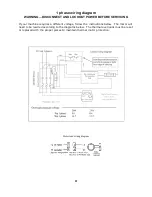
Reconnect the transformer in the magnetic starter as shown in the diagram on the
inside of the starter box cover. This is also found on pages 23
-
24
of this manual.
3.
Replace or adjust the thermal overload protectors (D) using dial (A), see below right)
with those rated at the desired amperage range. If the overloads trip you will need
to press reset button (C) to resume operation.
4.
Contact your dealer or customer service via phone at 800
-
733
-
4063 or email at
[email protected] for correct information on thermal overload
protectors.
Overload Protection
Your saw is equipped with automatic reset thermal overload protection. To restart after thermals
have tripped, wait until the motor cools, then press the saw start button. If overloads continue to
trip, the machine is being overloaded. Do not continue to operate under these conditions. This could
indicate an electrical problem take the time to find the trouble and correct it—see the electrical trou-
ble shooting section of this manual. The power supply branch circuit should be fused as follows us-
ing time delay fuses:
T1, T2, T3
Power out
to Motor
Overload
Block (D)
Thermal
setting
Dial (A)
Reset button
(C )
L1, L2, L3
Power In
from supply
Control Panel layout and components
Ground
Lug
1 Phase
3 Phase
3 Phase
3 Phase
Motor Horsepower
200
-
240 V
200
-
240 V
440
-
480 V
550
-
600 V
5
50
30
15
—
5
—
40
15
15
Содержание 3531-01
Страница 11: ...11 11...


