Method of control via Modbus protocol
−13−
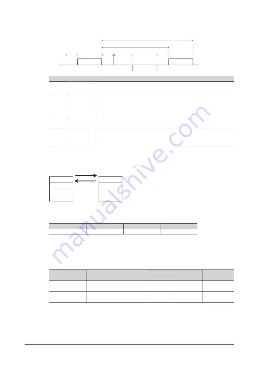
4.8 Communication timing
Query
Tb2
C3.5
C3.5
C3.5
Tb3 (Broadcast)
Tb1
Query
Response
Master
Slave
Character
Name
Description
Tb1
Communication
timeout
The interval of the received query is monitored. If no query could be received after the
time set with the "Communication timeout" parameter, a communication timeout alarm
is generated (initial setting: not monitored).
Tb2
Transmission
waiting time
This is the time after the slave switches its communication line to the transmission
mode upon receiving a query from the master, until it starts sending a response. The
transmission waiting time is set with the "Transmission waiting time" parameter (initial
setting: 10 ms).
The actual transmission waiting time corresponds to the silent interval (C3.5) plus
transmission waiting time (Tb2).
Tb3
Broadcasting
interval
This is the time until the next query is sent in broadcasting.
A time equivalent to or longer than the silent interval (C3.5) plus 5 ms is required.
C3.5
Silent interval
Be sure to provide an interval of 3.5 characters or more as the transmission waiting time.
If this waiting time is less than 3.5 characters long, the driver cannot respond.
The silent interval should be 5.5 ms or more when the transmission rate is 9600 bps. The
silent interval should be 3.5 ms or more when the transmission rate exceeds 19200 bps.
4.9 Message
The message format is shown below.
Slave address
Function code
Data
Error check
Slave address
Function code
Data
Error check
Master
Query
Response
Slave
Query
The query message structure is shown below.
Slave address
Function code
Data
Error check
8 bits
8 bits
4×8 to 37×8 bits
16 bits
•
Slave address
Specify the slave address (unicast mode).
If the slave address is set to “0,” the master can send a query to all slaves (broadcast mode).
•
Function code
The function codes and message lengths supported by the
BLV
Series driver are as follows.
Function code
Function
Message length (byte)
Broadcast
Query
Response
03h
Reading from a holding register(s)
8
7 to 37
Not possible
06h
Writing to a holding register
8
8
Possible
08h
Diagnosis
8
8
Not possible
10h
Writing to multiple holding registers
11 to 41
8
Possible
•
Data
Set data associated with the selected function code. The specific data length varies depending on the function code.


