


■ GSC-02A
User's Manual
■
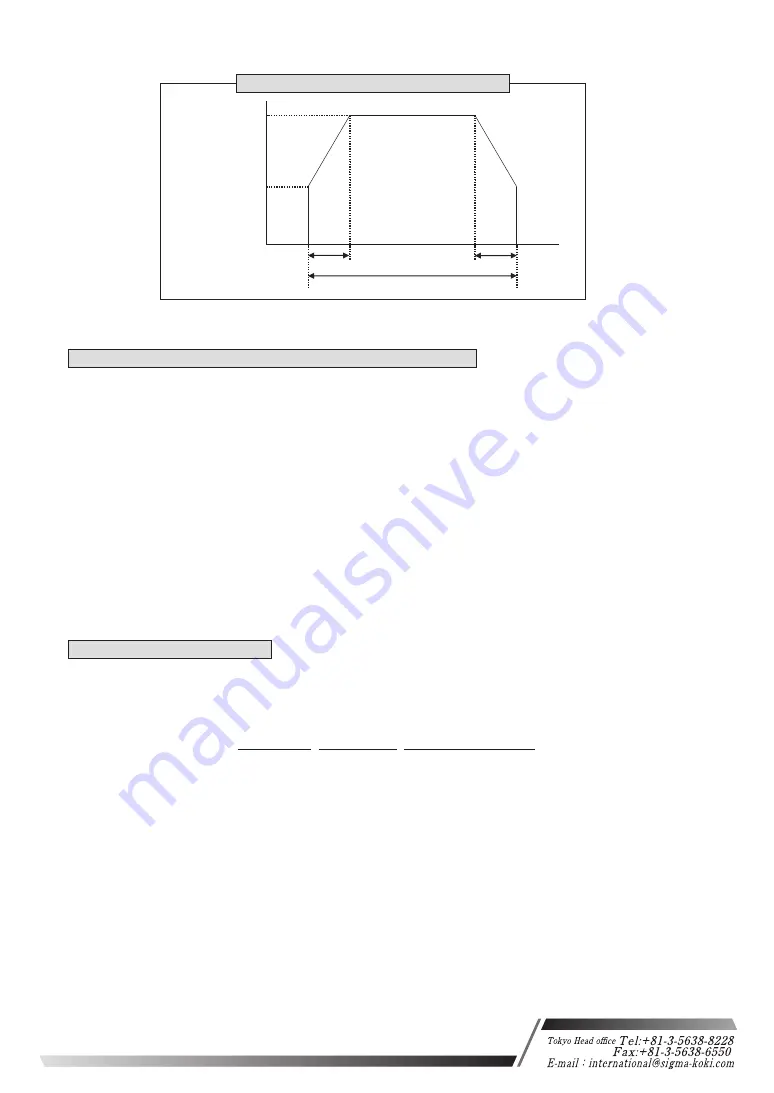
Acceleration and Deceleration Patterns
Number of
pulses moved
Positioning time
Maximum pulse
speed (F)
Minimum pulse
speed (S)
Deceleration
time (R) [ms]
Acceleration
time (R) [ms]
Figure7-3-1: Acceleration and Deceleration Patterns
(11) C command: Free/ hold motor (Excitation ON/OFF)
Features:
This command is used to excite the motor or to turn excitation off, making it possible
to move (rotate) stages manually.
・Command format
C:nm
・parameter
n: 1 or 2 or W
1: first-axis, 2: second-axis, W: both first-axis and second-axis
m: 0 or 1
0: electromagnetic current off, 1: electromagnetic current on
(If n is set to W, m needs to be set for two)
Ex1) C:10
Free first-axis motor
Ex2) C:W01
Free first-axis motor, and Hold second-axis motor.
Note) During stage operating status is Busy, the command status is NG.
Note) During all of electromagnetic current off by C command, motorized stages can't move and
the command status is NG.
(12) Q command: Status 1
Features:
On receipt of this command, the controller returns the coordinates for each-axis and
the current state of each stage.
・Command format
Q:Return data:
- 1000, - 20000, ACK1, ACK2, ACK3
ACK1:
X:Command or parameter errors.
K :Command received normally.
ACK2:
L :First-axis stopped at LS
M:Second-axis stopped at LS
W:First and second axes stopped at LS
K :Normal stop
ACK3:
B:(BUSY) L, Q, !, and ?, commands can be received
R:(READY) all commands can be received
Note) Coordinate values for each-axis have a fixed length of ten digits, including symbols
(Symbols are left-aligned, coordinates values right-aligned).
First-axis
coordinates
Second-axis
coordinates
Three-character
string data
15
Osaka branch


