I N S T A L L A T I O N
77 / 192
XS20000_31_manual_ger_eng_it_V1.1.2.doc
R. Kistler
3.5.2
Terminal strip
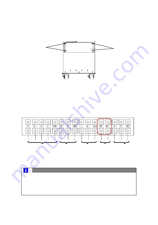
Please unscrew the four screws at the terminal cover for access to
the terminal strip (see Figure 5).
Figure 5: Terminal cover
Below the terminal cover are four openings for cable gland fittings,
3x 32 mm Ø and 1x 40 mm Ø. The cable gland fittings are not in-
cluded.
Connect the cables according to Figure 6.
Figure 6: Terminal strip
NOTE
For individual operation,
the jumper must be inserted be-
tween JP1 and JP2
(see Figure 6)
For parallel operation, the jumper must be removed from JP1
and JP2 (see Figure 6)
2 x
2 x
Line input
Input
Main 1
Output
Output
Bypass
Bypass
Main 2
Battery
Battery
Wire jumper
Jumper
Содержание 10000 3/1 XANTO S Series
Страница 2: ...2 192 XS10000 XS20000_31_manual_ger_eng_it_V1 1 2 doc R Kistler ...
Страница 64: ...64 192 XS10000 XS20000_31_manual_ger_eng_it_V1 1 2 doc R Kistler ...
Страница 66: ...66 192 XS10000 XS20000_31_manual_ger_eng_it_V1 1 2 doc R Kistler ...
Страница 126: ...T E C H N I C A L D A T A 126 192 XS10000 XS20000_31_manual_ger_eng_it_V1 1 2 doc R Kistler 9 3 CE conformity ...
Страница 128: ...128 192 XS10000 XS20000_31_manual_ger_eng_it_V1 1 2 doc R Kistler ...
Страница 130: ...130 192 XS10000 XS20000_31_manual_ger_eng_it_V1 1 2 doc R Kistler ...
Страница 190: ...D A T I T E C N I C I 190 192 XS10000 XS20000_31_manual_ger_eng_it_V1 1 2 doc R Kistler 9 3 Dichiarazione CE ...
Страница 192: ...192 192 XS10000 XS20000_31_manual_ger_eng_it_V1 1 2 doc R Kistler ...

