


8 - 57
8 Pulse Output Units
NX-series Position Interface Units User’s Manual (W524)
8-
10 Fu
nct
ions
8
8-1
0-3 Output Mod
e Selection
The velocity-continuous pulse output method is used to output pulses so that the specified velocity is
maintained.
However, at low velocities the response to changes in host commands is slower if the command veloc-
ity is strictly retained. For example, if a command velocity of 1 pps is given and retained strictly, the time
required to output one pulse would be one second, and during that time there will be no response even
if the command value changes.
You must also consider cases when a position command is given with a command velocity of 0 pps
(i.e., any speed less than 1 pps) according to the results of a deceleration command, such as when
positioning is stopped.
Therefore, when velocity-continuous pulse output is used, the command velocity has the characteristics
that are shown in the following table.
Precautions for Correct Use
If the command velocity is greater than 500 kpps, pulse output is performed at 500 kpps.
The command position for a Pulse Output Unit is given as signed, 32-bit data that expresses the abso-
lute position. It is the shortest distance in relation to the present position with a travel distance
expressed by up to 31 bits.
The maximum output velocity is 500 kpps, so pulse output is limited to a maximum of 500 kpps even if
a higher velocity is specified.
Therefore, depending on the commands that are received, the following error between the command
position and the present position can increase to a point where the following error exceeds 31 bits and
the operation begins to run in the reverse direction.
To avoid this, the following error between the command position and the present position is monitored
and an Illegal Following Error error event occurs if it exceeds 30 bits.
If an Illegal Following Error occurs during axis operation, the control state changes from Fault Reaction
Active to Fault. Pulse output is also stopped according to the Load Rejection Output Setting.
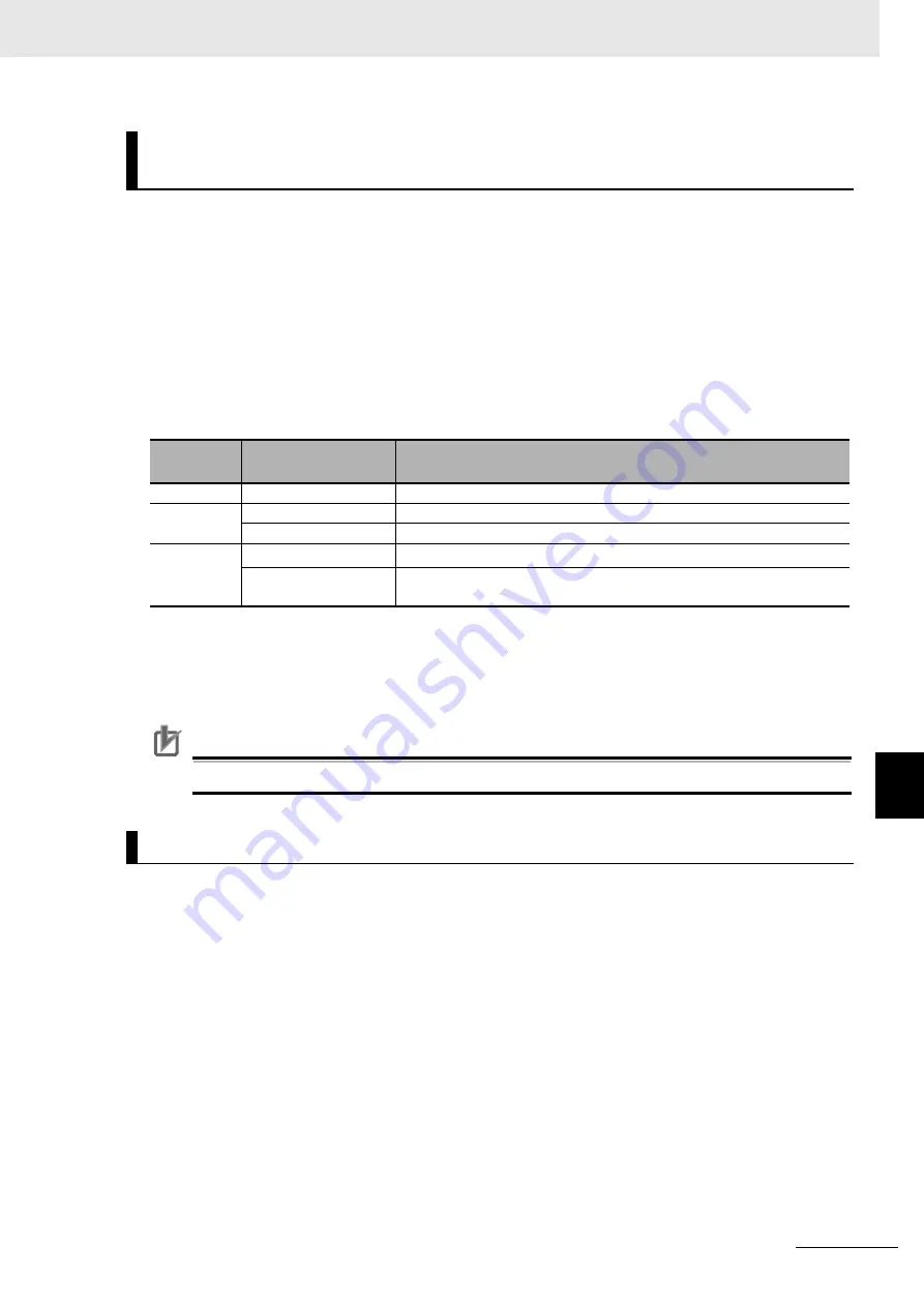
Low Velocity Command Operation for Velocity-continuous Pulse
Output
Travel dis-
tance
*1
*1. The travel distance is expressed as the amount of change from the previous command position.
Command velocity
Pulse output operation
0
---
No pulse output.
1
250 pps max.
Pulses are output at 250 pps.
251 pps min.
Pulses are output at the command velocity.
2 or higher
0
Pulses are output at the previous command velocity.
*2
*2. If the previous command velocity was 0, pulses are output at 1 pps.
1 pps min.
Pulses are output at the command velocity, with a maximum velocity of
500 kpps.
Monitoring the Following Error
Содержание NX-EC0112
Страница 13: ...11 Manual Structure NX series Position Interface Units User s Manual W524...
Страница 34: ...Revision History 32 NX series Position Interface Units User s Manual W524...
Страница 36: ...Sections in this Manual 34 NX series Position Interface Units User s Manual W524...
Страница 70: ...2 Specifications and Application Procedures 2 14 NX series Position Interface Units User s Manual W524...
Страница 78: ...3 Part Names and Functions 3 8 NX series Position Interface Units User s Manual W524...
Страница 108: ...4 Installation and Wiring 4 30 NX series Position Interface Units User s Manual W524 Unit...
Страница 114: ...4 Installation and Wiring 4 36 NX series Position Interface Units User s Manual W524...
Страница 126: ...5 I O Refreshing Methods 5 12 NX series Position Interface Units User s Manual W524...
Страница 340: ...8 Pulse Output Units 8 76 NX series Position Interface Units User s Manual W524...
Страница 462: ...Appendices A 74 NX series Position Interface Units User s Manual W524...
Страница 463: ...I 1 I NX series Position Interface Units User s Manual W524 Index...
Страница 466: ...I 4 NX series Position Interface Units User s Manual W524 Index...


