background image


Regular Payload Series-Hardware Installation Manual TM5 Series


35 

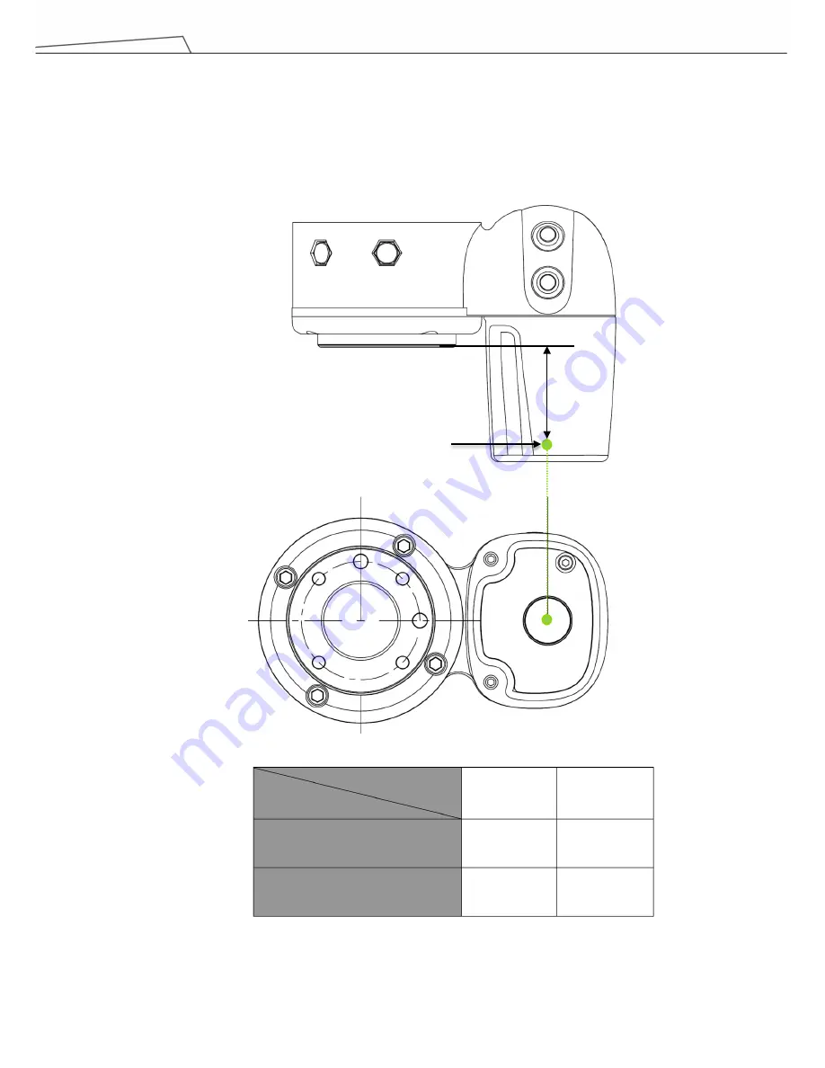
4.4 Working distance and field of view of TM Robot’s EIH camera 

The field of view of TM Robot’s EIH camera varies linearly in accordance with the working distance. The minimum 
working distance is about 100 mm and the maximum working distance is about 300 mm. The zero working 
distance point is approximately 49 mm in front of the flange surface and right behind the center of the protection 
lens.   


The relation between the working distance and the field of view is listed below, 


Working distance (mm) 

Field of view (mm) 

300 

100 

Width 

281.6 

96.9 

Height 

211.2 

72.7 


48.6


Working distance = 0 

Содержание Medium & Heavy Payload Series

Страница 1: ...Collaborative Robot Hardware Installation Manual Corresponding models TM5 Regular Payload Series Original Instruction I623 E 02...

Страница 2: ...ed in whole or in part without prior authorization from the Corporation No information contained herein shall be considered an offer or commitment The information herein is subject to change without n...

Страница 3: ...Power 12 2 10 Labels 14 3 Transportation and Storage 15 4 System Hardware 16 4 1 Overview 16 4 2 System Overview 16 4 2 1 Robot Arm 17 4 2 1 1 Dimension Drawings of Robot 17 4 2 1 2 Robot Assembly Di...

Страница 4: ...ort 47 5 4 Tool End I O Interface 48 5 4 1 I O Terminals 48 5 4 2 Connecting Tool End Digital Output 50 5 4 3 Connecting Tool End Digital Input 50 5 4 4 Connecting Tool End Analog Input 50 5 5 Control...

Страница 5: ...oad Series Hardware Installation Manual TM5 Series 5 6 4 3 Removal of the Robot Arm and Tightening 63 6 4 4 Connect the Robot and Control Box 65 7 Maintenance and Repair 66 Appendix A Technical Specif...

Страница 6: ...gular Payload Series Hardware Installation Manual TM5 Series 6 Revision History Table Revision Date Revised Content 01 October 2018 Original release 02 December 2018 Updated cover page minor text fixe...

Страница 7: ...st safety functionality 1 2 How Can I Get Help Additional information and resources are available at www adept com omron adept cobot manuals Related Manuals This manual covers the hardware installatio...

Страница 8: ...them when reading each paragraph and observe them to avoid personal injuries or equipment damage DANGER Identifies an imminently hazardous situation which if not avoided is likely to result in seriou...

Страница 9: ...he risk assessment may require the use of additional risk reduction measures If any local or national electrical regulation requires power to the robot and its power supply must be locked out and tagg...

Страница 10: ...ed information in the Manual shall not be considered as a guarantee that the product will not cause any personal injury or damage 2 6 General Safety Warning 1 The actual noise measured in a factory se...

Страница 11: ...n on the system controller When the user presses the emergency switch the TM Robot product will disconnect the power of robot and activate the brake after the robot motion is stopped The indication li...

Страница 12: ...as well as safety precautions refer and abide by the relevant chapters in the Safety Manual If the robot loses power and joints need to be moved in order to clear error conditions you will need to rel...

Страница 13: ...ion Manual TM5 Series 13 WARNING 1 Additional supports may be needed when manually releasing the brake due to gravity 2 When manually moving each robot joint the movement angle must be within a range...

Страница 14: ...d warnings of the labels when operating to keep the manipulator safely Do not tear damage or remove the labels Be very careful if you need to handle the parts where the labels are attached A Do not pu...

Страница 15: ...box cartons to avoid back injury OMRON will not be liable for any injuries cased during transportation WARNING This product must be shipped and stored in a temperature controlled environment within t...

Страница 16: ...l TM5 Series 16 4 System Hardware 4 1 Overview This chapter introduces the mechanical interface of the TM Robot System 4 2 System Overview TM Robot is made up of the robot arm and control box includin...

Страница 17: ...Regular Payload Series Hardware Installation Manual TM5 Series 17 4 2 1 Robot Arm 4 2 1 1 Dimension Drawings of Robot Shown below are the three view dimension drawings of the robot TM5 700 TM5M 700...

Страница 18: ...Regular Payload Series Hardware Installation Manual TM5 Series 18 TM5 900 TM5M 900...

Страница 19: ...TM5 Series 19 4 2 1 2 Robot Assembly Diagram Shown below is an illustration of the robot components To avoid safety risks do not attempt to disassemble any component on your own Contact your local OMR...

Страница 20: ...Regular Payload Series Hardware Installation Manual TM5 Series 20 TM5 900 TM5M 900...

Страница 21: ...be readily accessible during manual mode At least one emergency switch is installed outside of the motion range of the robot When no motion limit is set for the robot the motion range of the robot is...

Страница 22: ...Series Hardware Installation Manual TM5 Series 22 Pictorial view Operator Position Warning Risk of crushing within the operating area of the arm Warning Risk of collision within the operating area of...

Страница 23: ...Regular Payload Series Hardware Installation Manual TM5 Series 23 TM5 900 TM5M 900 Movement Range Pictorial view Side View...

Страница 24: ...ayload Series Hardware Installation Manual TM5 Series 24 Operator Position Warning Risk of crushing within the operating area of the arm Warning Risk of collision within the operating area of the arm...

Страница 25: ...wn below is an illustration of the robot hazard zone and operator position diagrams Do not operate the robot while anyone is inside of the hazard zone to avoid safety risks TM5 700 TM5M 700 Operator P...

Страница 26: ...ad Series Hardware Installation Manual TM5 Series 26 TM5 900 TM5M 900 Operator Position Warning Risk of crushing within the operating area of the arm Warning Risk of collision within the operating are...

Страница 27: ...its center of gravity offset which is defined as the distance from the center point of tool flange to the payload s center of gravity The following figure shows the relationship between payload and t...

Страница 28: ...40 Nm Optional Two openings for 6 mm position pins are provided for more secure position mounting DANGER 1 The TM Robot must be securely and tightly screwed down before use The strength of the mounti...

Страница 29: ...eries 29 4 2 2 Robot End Module 4 2 2 1 End Module Components GRIPPER Button Camera module Flange ISO 9409 1 50 4 M6 Digital I O Indication Light Ring Analog I O FREE Button VISION Button POINT Button...

Страница 30: ...Regular Payload Series Hardware Installation Manual TM5 Series 30 Digital l O Analog l O Camera 4 2 2 2 End Flange Surface...

Страница 31: ...recision you can use two positioning pins with a diameter of 6 mm for a more secure mounting 4 2 2 4 End Indication Light Ring Table The Indication Light Ring of the TM Robot has several colors which...

Страница 32: ...des for air flow 4 2 3 1 Robot Stick The Robot Stick has 6 function buttons 3 indicator lights 1 Emergency Switch and 1 QR code Their functions are as follow CAUTION When operating the robot stick do...

Страница 33: ...ing Booting Constant Startup completed Mode Indicator Lights One is Manual Mode the other one is Auto Mode They show the robot s current operating mode Once boot up is complete only one will always be...

Страница 34: ...obot stick The Robot Stick Stand should be fix with screws Always attach the robot stick when it is not in use The robot stick should be placed in a way such that the signal cables are routed to avoid...

Страница 35: ...stance The minimum working distance is about 100 mm and the maximum working distance is about 300 mm The zero working distance point is approximately 49 mm in front of the flange surface and right beh...

Страница 36: ...Ensure all pieces of the equipment are kept dry If water enters the equipment disconnect the power and contact your supplier 2 Only use the original cables included with the robot If you need longer c...

Страница 37: ...Installation Manual TM5 Series 37 5 3 Control Box WARNING Except for USB ports other interfaces have to be installed while arm is powered off Do not install while arm is on to avoid abnormal shutdown...

Страница 38: ...C contact Normally closed When any connected ESTOP switch is OPEN the robot enters the Emergency STOP state 2 Safeguard A Port is a N C contact Normally closed When Safety A switch is OPEN the robot e...

Страница 39: ...fety device and safety connector on TM Robot is preferred use a safety device with PNP outputs The PNP outputs can be connected to ether SAFETY_A1 and SAFETY_A2 or SAFETY_B1 and SAFETY_B2 to trigger t...

Страница 40: ...Regular Payload Series Hardware Installation Manual TM5 Series 40 The wiring diagram shows the example of PNP output type safety device...

Страница 41: ...und then it will switch to the internal 24V supply 2 The control box itself offers a 24V1 5A output 24_EX If the 24V load exceeds 1 5A it enters Safe Mode and disables the 24V output 3 EX24V provides...

Страница 42: ...t each has 16 channels and its application is connected to the following sections 5 3 3 1 Digital Input Inputs can be set to either sink input or source input by selection Set to sink input type When...

Страница 43: ...ce such as a transistor output sensor is connected PNP open collector transistor output can be used 5 3 3 2 Digital Output Outputs can be set to either sink output or source output by selection The ma...

Страница 44: ...Regular Payload Series Hardware Installation Manual TM5 Series 44 Set to sink output type Connect DO_COM terminal to the minus side of the power supply...

Страница 45: ...Regular Payload Series Hardware Installation Manual TM5 Series 45 Set to source output type Connect DO_COM terminal to the plus side of the power supply...

Страница 46: ...are Installation Manual TM5 Series 46 5 3 4 Analog In Analog In only supports a voltage mode and detection range of 10 00 V 10 00 V 5 3 5 Analog Out Analog Out only supports a voltage mode and detecti...

Страница 47: ...must be powered off when installing the EtherCAT Slave Do not plug or unplug the connector while the robot is on 5 3 8 USB Port The USB port of the control box is used for connecting the keyboard mous...

Страница 48: ...off the 24V output power 8 pin digital I O connectors of Cable 8 pin digital I O connector of Robot Pin Wire color Pin define 1 Brown 24v 24V output 2 Red DI_0 Digital Input0 3 Orange DI_1 Digital In...

Страница 49: ...I O connector of Robot Pin Wire Color Pin Define 1 Black 24V 24V output 2 Brown DI_3 Digital Input3 3 Red DO_3 Digital Output3 4 Orange AI Analog Input 5 Yellow 0V GND Pin Wire Color Pin Define 1 Bla...

Страница 50: ...tal Input The following figure shows how to connect the tool end digital input NOTE If sensors are connected directly then they should be NPN 5 4 4 Connecting Tool End Analog Input Input range of 10 0...

Страница 51: ...n only be used to connect ETHERCAT devices Improper connection may cause the robot to stop Robot Status Display USB3 0 2 COM1 Robot Cable Adapter USB 2 0 4 HDMI LAN for GigE Camera 2 EtherCAT Line out...

Страница 52: ...2 0 4 HDMI LAN for GigE Camera 2 EtherCAT Line out Air Filter Screw Power Remote ON OFF COM2 COM3 LAN Mic in I O Interface PE TM5M 700 SEMI TM5M 900 SEMI Series External Power Supply Remote Control DC...

Страница 53: ...power supply should be equipped with the following Grounding Main fuse Residual current device RCD It is recommended to install a master switch on the equipment power supply for robot applications fo...

Страница 54: ...C External mains fuse 100V 120V 15 A External mains fuse 220V 240V 8 A Input frequency 43 63 Hz Parameters Minimum Value Typical value Maximum value Unit Input voltage 22 60 V DC Power consumption 200...

Страница 55: ...n the robot 2 Do not extend or modify the original cables of the robot 3 The cables of the robot are only suitable for a fixed installation If you require a flexible installation contact OMRON 5 6 3 C...

Страница 56: ...or external damage as it is removed from its container If any damage is evident contact your OMRON support see HOW Can I Get Help on 1 2 Retain all shipping containers and packaging materials These it...

Страница 57: ...es Hardware Installation Manual TM5 Series 57 6 3 Unboxing 6 3 1 Carton Types The TM Robot product is packed in 2 cartons the robot arm carton and the control box carton as shown below Robot arm carto...

Страница 58: ...lation Manual TM5 Series 58 6 3 2 Contents of Each Carton Each carton has the following contents Check them when you unpack the cartons for the first time If any item is missing contact your vendor Th...

Страница 59: ...tallation Manual TM5 Series 59 The control box carton contains IO cables 2 packs 8 pin digital I O 5 pin analog I O Calibration Plates Contains one large and one small calibration plate TM Landmark Co...

Страница 60: ...e Installation Manual TM5 Series 60 1 cable Power cable of the control box TM5M 700 TM5M 900 4 cables Type B I G F Power cable of the control box TM5 700 TM5 900 Ground Wire 1 pack SEMI Emergency OFF...

Страница 61: ...t arm damage or personal injury Do not install the robot alone WARNING Do not attempt to move any robot links until the robot has been secured in position Failure to comply could result in the robot f...

Страница 62: ...One should hold on to the control box handles while the other should carry the foot stands Before handling the cable of the robot stick should not be pulled to avoid any performance degradation WARNIN...

Страница 63: ...figure shown below Place the robot on the mounting base If it is designed with connection pins align the pinholes of the robot base module Tighten two locking screws with metal washers for the robot...

Страница 64: ...attention to your safety to avoid pinching If you do not have connection parts at hand such as the connecting pins screws do not leave the robot without completely tightening it with the 4 screws com...

Страница 65: ...wer to the control box to boot up the controller WARNING 1 Ensure that all cables are correctly connected before the control box is energized Always use genuine power cables correctly 2 When the robot...

Страница 66: ...ll be constantly flashing When the Safeguard B Port is in the open loop state the purple light will be alternating between the indication light of the current mode Check Robot Mounting Screws 3 months...

Страница 67: ...grees of freedom 6 rotating joints I O ports Control box 16 16 2 1 Tool conn 4 4 1 0 Digital in Digital out Analog in Analog out I O power supply 24V 1 5A for control box and 24V 1 5A for tool IP clas...

Страница 68: ...68 I623 E 02 19888 100 B 1218 1018...

Отзывы: