


zipldr_setup&operations
www.OmniTurn.com
(541) 332-7004
(541)-332-1018 fax
Fast... Precise... A
ff
ordable...
Zip Loader Setup & Operations
Omni
Turn
Page 15 of 44
Loader Alignment and Changing Diameters
The procedure for aligning the “vee” of the loader to centerline of the spindle is critical
because the loader is designed so that different bar diameters will be on center by pivoting
the entire tray and ’vee’ assembly. With tray assembly is at its lowest position, set the load-
er height so that 1-1/8” bar will slide easily into draw-tube on OmniTurn. If a liner is in-
stalled, the same 1-1/8” bar can be used with tray assembly at lowest position, but a dowel
that closely fits liner must be installed on center in bar.
No other adjustment is necessary to put different diameters on center if this ini-
tial alignment is properly done.
Parts with diameter less than 1/4” will probably
require some additional adjustment to insure consistent feeding.
To accommodate different bar diameters, adjust the distance of the ‘vee’ from the knife,
and pivot the entire tray to bring the new diameter on center. Knurled black-plastic adjust-
ment knobs on each side of tray lock the ‘vee’ in place, and a single steel tray-lock knob on
the left side locks the centerline adjustment.
For small diameter parts it may be necessary to ‘tweak’ the loader to insure reliable feeding.
See next page: “Aligning the OmniTurn ZipLoader for Small Diameter Parts”.
Special pushrods are necessary for parts less than 1/4” diameter. See pages 14 & 15 for
more information about these pushrods.
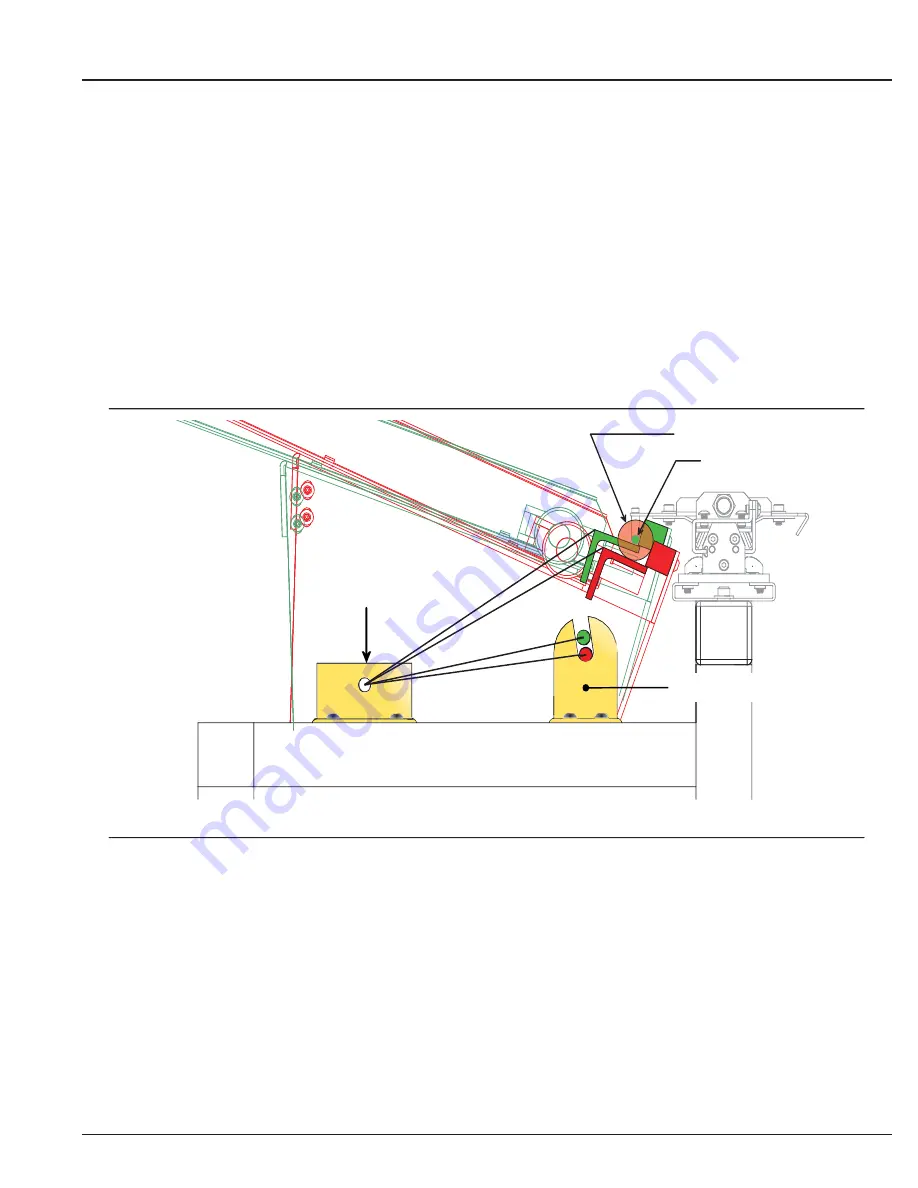
RED=Tray at lowest position
GREEN=Tray raised for 1/4” part
1-1/8” alignment bar
Tray Lock Bracket
Pivot Bracket
1/4” part
As tray pivots, centers of different diameter parts align with pusher and spindle-liner.


