Y101700-5
Service Manual
5-1
5.
ADJUSTMENTS
5.1 Image distortion adjustment
There are following two types of image distortion.
• Horizontal image distortion
• Vertical image distortion
In this machine, the image distortion is adjusted by
changing the parallelism of mirrors (copy lamp unit,
No. 2/3 mirror unit).
5.1.1 Horizontal image distortion adjustment
Parallelism of mirrors can be made by installing the copy
lamp unit and No. 2/3 mirror unit to the reference position.
However, it must be checked by making a copy, and
must be adjusted if necessary.
5.1.1.1 Cases when the adjustment is required
1) When the copy lamp unit and No.2/3 mirror unit are
disassembled or their part is replaced.
2) When the copy lamp unit and No.2/3 mirror unit drive
section is disassembled or its part is replaced.
3) When the copy image is distorted as shown below:
5.1.1.2 Necessary tools
• Screwdriver (+)
• Hex wrench
• Scale
• Test chart for distortion adjustment (Make a chart
shown below by yourself.)
Draw a rectangle on a paper (B4 or 8 1/2” x 14”)
as shown below.
Be sure to make four right angles.
5.1.1.3 Adjustment procedure
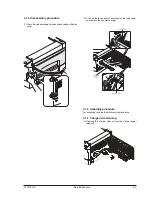
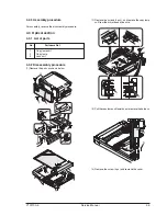
1) Remove the right cabinet (manual paper feed unit), the
document reference plate.
2) Remove the document glass.
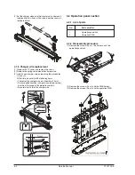
3) Loosen the fixing screw of the copy lamp unit wire.
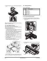
4) Manually turn the copy lamp unit/No.2/3 mirror unit drive
gear to bring No.2/3 mirror unit into contact with No.2/3
mirror unit positioning plate. When No.2/3 mirror unit
makes contact with No.2/3 mirror unit positioning plate in
the Freat and rear frameside simultaneously, the
mechanical parallelism of No.2/3 mirror unit is proper.
If one side of No.2/3 mirror unit makes contact with
No. 2/3 mirror unit positioning plate and the other side
does not, the parallelism is improper.
If the parallelism is improper, perform the procedure of
step 5.
Содержание d-Copia 12
Страница 1: ...d Copia 12 Copier SERVICE MANUAL Code Y101700 5 ...
Страница 4: ...vi Service Manual Y101700 5 ...
Страница 18: ...Service Manual Y101700 5 1 14 ...
Страница 72: ...Y101700 5 Service Manual 7 1 7 MAINTENANCE 7 1 Maintenance table 7 2 Maintenance display system ...
Страница 73: ...Service Manual Y101700 5 1 14 ...
Страница 74: ...Y101700 5 Service Manual 8 1 8 ELECTRICAL SECTION 8 1 Block diagram 8 1 1 Overall block diagram ...
Страница 75: ...8 2 Service Manual Y101700 5 8 2 MCU PWB unit ...

