4-12
Service Manual
Y101700-5
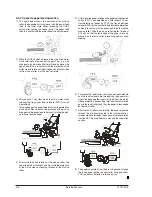
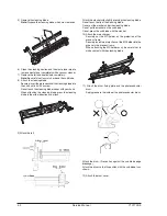
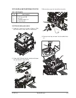
(13) Remove two screws and remove the fusing connector.
(14) Remove five screws and the connector, and lift the
intermediate frame unit to remove.
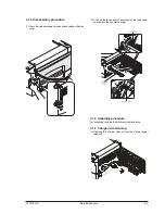
(15) Remove the screw and the E-ring, and remove the PS
semi-circular earth plate and the PS roller unit.
(16) Remove the E-ring and remove the spring clutch from
the PS roller unit.
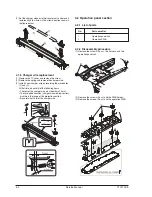
(17) Remove three screws and remove the TC front paper
guide.
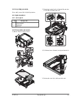
(18) Remove the screw and the connector, and remove the
PPD1 sensor PWB.
Содержание d-Copia 12
Страница 1: ...d Copia 12 Copier SERVICE MANUAL Code Y101700 5 ...
Страница 4: ...vi Service Manual Y101700 5 ...
Страница 18: ...Service Manual Y101700 5 1 14 ...
Страница 72: ...Y101700 5 Service Manual 7 1 7 MAINTENANCE 7 1 Maintenance table 7 2 Maintenance display system ...
Страница 73: ...Service Manual Y101700 5 1 14 ...
Страница 74: ...Y101700 5 Service Manual 8 1 8 ELECTRICAL SECTION 8 1 Block diagram 8 1 1 Overall block diagram ...
Страница 75: ...8 2 Service Manual Y101700 5 8 2 MCU PWB unit ...

