Y101700-5
Service Manual
4-1
4. DISASSEMBLY AND ASSEMBLY
Before disassembly, be sure to disconnect the power cord
for safety.
The disassembly and assembly procedures are described
for the followingn sections:
1. High voltage section
2. Operation panel section
3. Optical section
4. Fusing section
5. Cassette paper feed/transport section
6. Manual paper feed section
7. Rear frame section
8. Power section
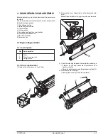
4.1 High voltage section
4.1.1 List of parts
No.
Part name Ref.
1
Drum
2
Transfer charger unit
3
Charger wire
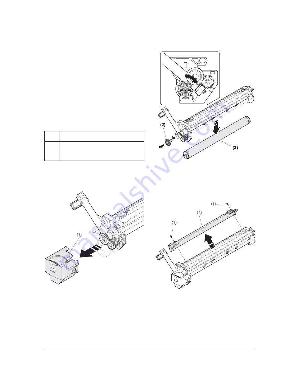
4.1.2 Drum replacement
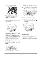
1) Remove the drum cover. (4 Lock Tabs)
2) Remove the drum fixing plate and the photoconductor
drum.
Note:
Dispose the drum fixing plate which was removed.
3) Check the cleaning blade and the red felt for no damage.
• If there is any damage, execute all procedures from
item 5) and later.
• If there is no damage, execute the procedure of item 12).
4) Remove the main charger.
(Cleaning the screen grid and the sawteeth.)
Содержание d-Copia 12
Страница 1: ...d Copia 12 Copier SERVICE MANUAL Code Y101700 5 ...
Страница 4: ...vi Service Manual Y101700 5 ...
Страница 18: ...Service Manual Y101700 5 1 14 ...
Страница 72: ...Y101700 5 Service Manual 7 1 7 MAINTENANCE 7 1 Maintenance table 7 2 Maintenance display system ...
Страница 73: ...Service Manual Y101700 5 1 14 ...
Страница 74: ...Y101700 5 Service Manual 8 1 8 ELECTRICAL SECTION 8 1 Block diagram 8 1 1 Overall block diagram ...
Страница 75: ...8 2 Service Manual Y101700 5 8 2 MCU PWB unit ...


