17
GB
• A grounded electrical connection is obligatory (if the cable issued with the stove is not
long enough to reach the closet socket, use an extension cable along the floor).
Fire Safety Distance
The stove must be installed respecting the following safety conditions:
• Minimum distance from the sides and the back must be 40 cm from moderately in-
flammable material;
• Easily inflammable material must not be place closer than 80 cm in front of the stove;
• If the stove is installed on an inflammable pavement the stove must be placed on a
slab of material that insulates it from the heat that is wider at the sides by 20 cm and
in the front by 40 cm;
• Do not place objects in inflammable material or any material that can compromise
the operation of the stove on the stove or within the safety distance;
• In addition, it is advisable to keep all elements of combustible or inflammable material
such as beams, wooden furniture, drapes, inflammable liquids, etc. outside the ra-
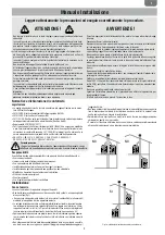
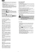
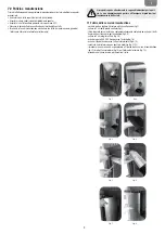
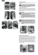
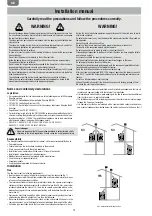
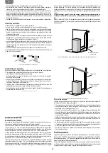
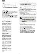
diance area of the stove, and in any case at least 1 m from the heating block (Fig. 8);
• In case of connection to wooden walls or other inflammable material, it is necessary
to insulate the smoke discharge tube with ceramic fibre or another material with the
same characteristics.
The combustion air must be taken from the outdoor ambience absolutely.
For a correct and safe placement of the air intake all the measures and prescriptions
(Fig. 9) must be respected.
There are distances to respect to prevent the comburant air from being subtracted from
another source: for example the opening of a window could cause eddies in the outside
air subtracting it from the stove.
Lighting
• Before lighting the stove, carefully read the use and maintenance manual.
• Remove from the tank all the tools that were inserted during packaging and be sure
that the tank is free of eventual extraneous bodies.
• Unroll the environmental probe placed on the rear of the stove, without placing it on
the heated parts of the stove.
• Correctly connect the pellet stove to the flue.
• Fill the tank with 6mm diameter pellets.
• Open the door and check that the basket is properly inserted in its slot and that the
flame trap is located in the upper part of the combustion chamber.
• Close the door. Never open the door while the pellet stove is operating.
• Connect the stove to an outlet with the appropriate cable received with the stove.
• Place the switch on the rear of the stove at the “1” position.
• Press the ON/OFF key for 2 seconds and the gearcase will begin its lighting cycle.
ATTENTION:
During the first lighting it is necessary to ventilate the environment well, since
during the first hours of operation unpleasant odours could develop due to fumes
from the paint and the grease in the tuyère wrapping.
If during the normal operation of the stove, the temperature of the smoke reaches 220°C
(parameter which can be modified by a technician) the smoke is modulated as follows:
• Smoke removal motor set at the maximum speed;
• Pellet loading gear motor at the minimum speed;
• Tangential heat exchange fan at the maximum speed.
This procedure functions to lower the temperature of the smoke. When this returns below
the level of 220°C the stove will restore the speed of the three motors returning them
to the settings before the level was passed.
If the electrical current cuts out, once it is restored, the display will indicate a state of
anomaly and will read “Black out”. The suction will be increased to expel the residual
smoke.
Operations to be performed by the Authorized Assistance Centre
every season before the lighting
• A general cleaning inside and outside.
• A careful cleaning of the exchange tubes.
• A careful cleaning and disincrustation of the crucible and the relative cavity.
• Clean the motors, checking the play and fastenings of the mechanisms.
• Clean the smoke channel (substitute the tube gaskets) and smoke extractor fan ca-
vity.
• Clean pressure switch, sostitute silicone tube.
• Check the probe.
• Replace the batteries in the clock on the electronic board.
• Clean, inspect and disincrust the lighting resistor compartment, replacing it if neces-
sary.
• Clean/check the synoptic panel.
• Visually inspect the electrical cables, the connections and the electrical power cable.
• Clean the pellet container and verify the play with the screw feeder gear motor.
• Replace the door seals.
• Test functions, loading the screw feeder, lighting, 10 minutes of operation and shut
down.
• Check the electrical parts and the electronic components.
• Check and possible cleaning of the canalisation.
WARNING
• Use of this device is subject to all local and national regulations as well as European
regulations.
• The installation of this device is subject to all local and national regulations as well as
European regulations.
• Do not pour the Pellets directly into the brazier
• To load the Pellets, open the tank lid positioned on the upper part of the stove and ca-
refully empty the Pellets’ package inside.
• Before pouring the Pellets inside the tank, please make sure that the stove is turned
off.
•
Should the stove overheat, a safety device will engage and block the feeder me-
chanism. After the stove’s cool-down cycle has been completed, re-engage the
thermostat placed at the back of the stove, by removing the thermostat’s cap
and pressing the button underneath. In case of repeated malfunctions, please
contact authorized technical support.
• The device is not intended for users (children included) whose physical or mental abi-
lities are reduced or by users who lack the proper knowledge or experience, unless
they have been instructed by a person responsible of their safety on the proper use of
this device and all the security measures. Children have to be supervised so that they
do not play with the device.
• Use only Pellets recommended by the manufacturer, of a diameter not exceeding 6mm
and a length not exceeding 30mm.
• Please store the Pellet in a dry environment.
Fig. 8: minimum distance of objects
Fig. 9: distanc from walls
Combustion
air inlet
walls
Thermostat’s cap
e
Minimum aeration for comburant air intake
Содержание MIA 2-11
Страница 1: ...MIA 2 9 MIA 2 11...
Страница 2: ......
Страница 5: ...5 I MIA 2 9 MIA 2 11 475 1050 520 227 133 390 340 50 80 110 455...
Страница 13: ...13 I...
Страница 16: ...16 GB MIA 2 9 MIA 2 11 475 1050 520 227 133 390 340 50 80 110 455...
Страница 24: ...24 GB...
Страница 27: ...27 F MIA 2 9 MIA 2 11 475 1050 520 227 133 390 340 50 80 110 455...
Страница 35: ...35 F...
Страница 38: ...38 D MIA 2 9 MIA 2 11 475 1050 520 227 133 390 340 50 80 110 455...
Страница 46: ...46 D...
Страница 49: ...49 E MIA 2 9 MIA 2 11 475 1050 520 227 133 390 340 50 80 110 455...
Страница 57: ...57 E...
Страница 58: ......
Страница 59: ......
Страница 60: ...278960A...

