background image

15

GB

is easily opened and inspected through the air-tight door.

• Whenever flues with parallel exits are used it is advisable to raise the upwind chamber

by one element.

• The chimney tube must never pass across a combustible surface.

The Chimney Cap

The chimney cap must respect the following requirements:
• It must have the equivalent diameter and internal form of the flue.
• It must have a useful outlet diameter of not less than double that of the flue.
• The chimney cap on the roof or that remains in contact with the outside (for example,

in case of open lofts or attics), must be covered with elements in brick or tile and
must, in any case, be well insulated.

• It must be constructed to prevent rain, snow, and extraneous bodies from entering the

flue and so that the discharge of the products of combustion is not inhibited by wind
from any quarter or strength (windproof chimney cap).

• The chimney cap must be positioned in such a way as to guarantee the adequate di-

spersion and dilution of the products of combustion and in any case, must be out of
the reflux zone. This zone has different dimensions and forms according to the angle
of inclination of the roof so it is necessary to adopt minimum heights (Fig. 2).

• The chimney cap must be a wind-proof type and must be above the ridge.
• Eventual structures or other obstacles that are higher than the chimney cap must not

be too close to the chimney cap itself.

Canalisation (if available)

Before you connect the auxiliary pipes for the canalisation of the air, please check that:
• The canalisation system is according to law.
• The system does not present any obstructions.
• Once you connect the stove and use the air ducting, there is a regular air flow at the

end of the canalisation.

• You can use up to two hot air delivery pipes with a maximum lenght of 4 m. each. If

you use only one pipe, the maximum lenght is 5 m. For more information see chapter
6.0.

• The piping and conduit must be protected with fixed, non-reclosable grids or suitable

covers. The minimal section must not be reduced anyway.

Sizing

Smoke discharge

The discharge system must be for the stove only (it is not permissible to discharge into
flues in common with other devices). The smoke discharge takes place through the 8
cm diameter tube placed at the back. A “T” with a condensation collection cap should
be provided. The smoke discharge of the stove must be connected with the outside
using a steel or black tube (resistant up to 450°C) without obstructions.
The tube must be hermetically sealed. To make the tubes airtight and for their eventual
insulation, it is necessary to use material resistant up to at least 300°C (silicone or putty
for high temperatures). The horizontal sections can be up to 2 m long. It is possible to
have up to three 90° curves. 
If the smoke duct is outside it must be insulated (Fig.4). 
If the smoke duct is inserted in a flue (Fig.3), this must be certified for solid combustibles
and if it is larger than 150 mm in diameter, modification is necessary by inserting a tube
and sealing the discharge with respect to the parts in brickwork.
It must be possible to inspect all the sections of the smoke duct. If it is a fixed duct it
must have openings for inspection and cleaning. 

The adjacent locale must not be used as a garage or be a space without ventilation
or air exchange, a storage area for combustible material or used for an activity
that has a fire hazard.

According to the norm UNI 10683/98, the stove must not be in

the same environment where extractors, type B gas devices or in any case, devices that
create lower atmospheric pressure in the locale are found.

External air intake

The stove must be furnished with the air necessary to guarantee the regular functioning
of the combustion and an environmental well being.
• Be sure that the room where the stove is installed has sufficient aeration and, if ne-

cessary, install an air intake duct with a minimum recommended diameter of 50 mm
and max length 1,5 m to bring in air from the outside.

• The external air intake must communicate with the stove and positioned so that it is

not obstructed. It must be protected with a permanent non-closable grill or other sui-
table protection provided that the minimum diameter is not reduced.

• The air flow can also be acquired from a locale adjacent to where the stove is installed

as long as that flow can freely cross the permanent non-closable openings that com-
municate with the outside.

• The presence in the local adjacent to where the stove is installed, of other devices in

use or of suction devices that cause a contrary draught effect must not create a lower
air pressure in the locale than in the outside environment.

• In the adjacent locale the permanent openings must respond to the requisites which

are listed in the points above.

Positioning

The stove is furnished with an electrical cable to connect to a 230V 50Hz socket, pre-
ferably with a thermal-magnetic switch. Variations in tension of more than 10% can
compromise the stove (if not already present, an adequate differential switch should be
provided). The electrical system must comply with the norms; verify in particular the ef-
ficiency of the ground circuit. The electrical feed cable must be of a diameter adequate
to the power of the device. The stove must be completely level. Verify the weight bearing
capacity of the flooring. 
The placement of the stove within the living environment is determined so that the en-
vironment is heated in a uniform manner.
Before deciding where to place the stove, keep in mind that:
• The air used for combustion must not come from a garage or a space without venti-

lation or air exchange, but from a free space or the outside;

• The stove should not be installed in a bedroom;
• Rather it is preferable to install the stove in a large, central room of the house to insure

the maximum heat circulation;sicurare la massima circolazione del calore;

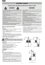
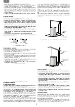
Fig.2: characteristics of the chimney cap

NO

SI

Fig.3: internal flue installation to do according to norms

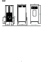
Air intake

min. 1,5 m

Condensation collection cap

Air intake

Condensation collection cap

Presa d’aria

Insulated tubing

Содержание MIA 2-11

Страница 1: ...MIA 2 9 MIA 2 11...

Страница 2: ......

Страница 3: ...ne d aria o opportuno isolante t La sezione interna deve essere uniforme preferibilmente circolare le sezioni quadra te o rettangolari devono avere spigoli arrotondati con raggio non inferiore a 20mm...

Страница 4: ...perature I tratti orizzontali possono avere lunghezza no a 2 m possibile un numero di curve a 90 no a tre Se il canale da fumo all esterno deve essere coibentato Fig 4 Se il canale da fumo si inserisc...

Страница 5: ...5 I MIA 2 9 MIA 2 11 475 1050 520 227 133 390 340 50 80 110 455...

Страница 6: ...odi cabile dal tecnico si ha la modulazione dei fumi come segue motore estrazione fumi impostato alla massima velocit motoriduttore di caricamento pellet alla minima velocit ventilatore tangenziale di...

Страница 7: ...le ns stufe viene provata l accensione in linea t La stufa deve essere alimentata solo con pellet di qualit del dia metro di 6 mm del tipo raccomandato dal costruttore t Prima di collegare elettricam...

Страница 8: ...ili Tramite i tasti 1 e 2 diminuire o aumentare il valore voluto L uscita dal men Set potenza avverr in maniera automa tica dopo alcuni secondi di inattivit all interno del men stesso Prima dell accen...

Страница 9: ...1 svitare le 2 viti della parete centrale g 2 tirare la parete verso l esterno e contemporaneamente sostenere ed estrarre il batti amma che si trova nella parte superiore g 3 4 svitare le 2 viti e to...

Страница 10: ...llet diversi da quelli consigliati dal produttore La periodicit di questa operazione determinata dalla frequenza di utilizzo e dalla scelta del pellet bene controllare anche il supporto braciere aspir...

Страница 11: ...Rimuovere tutti i pellet dal serbatoio e dalla coclea Pulire accuratamente il braciere il supporto braciere la camera combustione e il cas setto cenere Se i punti precedenti sono stati osservati ci c...

Страница 12: ...nimo massimo 10 12 Pa Tensione 230 V Frequenza 50 Hz Potenza assorbita in accensione 280 W Potenza assorbita a regime 100 W Peso con porta 83 kg Modello MIA 2 9 Potenza in ingresso min max 2 09 kW 8 5...

Страница 13: ...13 I...

Страница 14: ...of an air cavity or opportune insulation t The internal section must be uniform preferably circular the square or rectangular sections must have rounded corners with a radius of no less than 20 mm a...

Страница 15: ...ter modi cation is necessary by inserting a tube and sealing the discharge with respect to the parts in brickwork It must be possible to inspect all the sections of the smoke duct If it is a xed duct...

Страница 16: ...16 GB MIA 2 9 MIA 2 11 475 1050 520 227 133 390 340 50 80 110 455...

Страница 17: ...moval motor set at the maximum speed Pellet loading gear motor at the minimum speed Tangential heat exchange fan at the maximum speed This procedure functions to lower the temperature of the smoke Whe...

Страница 18: ...construction line t The stove must only be fed with quality 6mm diameter pellets of the type recommended by the manufacturer t Before making the electrical connection of the stove the discharge tubes...

Страница 19: ...d this means that the stove has begun the last phase in lighting at the end of which the stove will be completely opera switched off After several minutes of ventilation the display will read O 1 2 3...

Страница 20: ...brazier and the ash tray g 1 unscrew the 2 screws in the central bulkhead g 2 pull the central bulkhead towards outside and at the same time support and take off the re heater placed on the upper par...

Страница 21: ...omes also depends on the quality and quantity of pellets used Cleaning the glass should be done when the stove is cold with products recommended and tested by our company When performing this operatio...

Страница 22: ...ant to a thermal shock of 750 C the glass can break only from a strong impact or from improper use Do not slam the door or hit the glass In case of breakage replace the glass only with an original rep...

Страница 23: ...sumption working 2 09 kW 10 kW 8 88 kW 2 0 kW 88 78 95 48 154 2 C 52 3 C 10 12 Pa 230 V 50 Hz 280 W 100 W 83 kg Model MIA 2 9 Heating input min max Nominal heat output Reduced heat output CO emissions...

Страница 24: ...24 GB...

Страница 25: ...o le chaudi re ou hotte aspirante de tout type que ce soit g 1 t Doit tre ad quatement cart de mat riaux combustibles ou in ammables au moyen d interstice d air ou d un isolant ad quat t La section in...

Страница 26: ...Pour l tanch it des tubes et leur isolation ventuelle il est n cessaire d utiliser des mat riaux r sistant au moins 300 C silicone ou mastique pour haute temp rature Les parties horizontales peuvent a...

Страница 27: ...27 F MIA 2 9 MIA 2 11 475 1050 520 227 133 390 340 50 80 110 455...

Страница 28: ...nant du vernis et de la graisse dans les tubulures Si durant le fonctionnement normal du po le la temp rature des fum es atteint les 220 C param tre modi able par le technicien on a la modulation des...

Страница 29: ...QP MF QFOEBOU MF GPODUJPOOFNFOU t PSTRVF le po le fonctionne les surfaces la vitre les poign es et les conduites sont br lantes durant le fonctionnement ne pas tou cher ces parties sans protections a...

Страница 30: ...Temp rature les valeurs changent automatiquement apr s quelques secondes d inactivit s l int rieur du menu lui m me r siduels des pr c dents combustions En cas contraire vider et nettoyer le m me rvo...

Страница 31: ...cendrier voir g 1 d visser les 2 vis de la paroi centrale voir g 2 tirer la paroi vers l externe et en m me temps soutenir et enlever la plaque foy re qui est situ e dans la partie sup rieure g 3 4 d...

Страница 32: ...le L encrassement de la vitre d pend en outre de la qualit et de la quantit du pellet utilis Le nettoyage de la vitre doit tre effectu lorsque le po le est froid avec des produits conseill s et test s...

Страница 33: ...tre peut se briser suite un fort impact ou une utilisation incor recte Ne pas frapper la porte ni cogner la vitre En cas de bris remplacer la vitre uniquement par une pi ce de rechange d origine fourn...

Страница 34: ...ique absorb e en fonction 2 09 kW 10 kW 8 88 kW 2 0 kW 88 78 95 48 154 2 C 52 3 C 10 12 Pa 230 V 50 Hz 280 W 100 W 83 kg Mod MIA 2 9 Puissance thermique globale min max Puissance thermique nominale Re...

Страница 35: ...35 F...

Страница 36: ...der Abzugshauben haben Bild 1 t Er muss einen Sicherheitsabstand von Brennmaterialien durch eine passende Lufti solierung halten t Der innere Teil muss gleichf rmig lieber rund sein die viereckigen un...

Страница 37: ...er von 8cm der sich auf der hinteren Seite be ndet Am Anfang der R hre mu ssten Sie ein T mit Kondensatwasserwanne installieren Das Abgas des Ofens muss mit dem Au en durch Stahl oder Schwarzr hren bi...

Страница 38: ...38 D MIA 2 9 MIA 2 11 475 1050 520 227 133 390 340 50 80 110 455...

Страница 39: ...Sie den Knopf ON OFF fu r 2 Sekunden und die Platine f ngt die Zu ndungsprozedur an ACHTUNG Sie brauchen den Raum w hrend der ersten Einschaltung zu belu ften da es schle chte Geru che in den ersten S...

Страница 40: ...lektrischen Anschluss des Ofens sollen Auslassleitungen mit dem Rauchfang verbunden werden t JFNBMT EBT JUUFS JN Pelletbeh lter wegnehmen t Im Raum wo der Ofen installiert wird soll gen gende Luftzirk...

Страница 41: ...lay Die Taste zwei Sekunden lang dr cken Kurz danach wird der Abgasventilator sowie der Einschaltwiderstand aktiviert Es erscheint die Z nder LED leu chtet auf Nach zirka einer Minute erscheint der Of...

Страница 42: ...Drehen Sie die beiden Schrauben der Trennwand auf siehe Bild 2 Ziehen Sie die zentrale Trennwand nach au en und gleichzeitig st tzen und nehmen Sie den Feuererhitzer der sich oben be ndet siehe Bild 3...

Страница 43: ...Pellets ab Das Glas soll an dem kalten Ofen mit von unserer Firma em pfohlenen und gepr ften Produkten gereinigt werden Wenn Sie solche T tigkeit vor nehmen berpr fen Sie immer dass die Dichtung um d...

Страница 44: ...e eines heftigen Aufschlags bzw eines unsachgem en Gebrauchs Niemals die T r zuschlagen oder gegen das Glas sto en Im Fall eines Bruches ersetzen Sie das Glas nur mit einem durch den Autorisierten Te...

Страница 45: ...brauch bei Betrieb 2 09 kW 10 kW 8 88 kW 2 0 kW 88 78 95 48 154 2 C 52 3 C 10 12 Pa 230 V 50 Hz 280 W 100 W 83 kg Mod MIA 2 9 Globalheizleistung min max Nennheizleistung Reduzierte Leistung CO Werte m...

Страница 46: ...46 D...

Страница 47: ...de aire o un aislamiento oportuno La secci n interna deber ser uniforme preferiblemente circular las secciones cua dradas o rectangulares deber an tener esquinas redondeadas con un radio mayor de 20...

Страница 48: ...xterior utilizando un tubo de acero o negro resistente hasta una temperatura de 450 C sin obstrucciones El tubo deber estar herm ticamente sellado Para hacer que los tubos sean estancos y para su aisl...

Страница 49: ...49 E MIA 2 9 MIA 2 11 475 1050 520 227 133 390 340 50 80 110 455...

Страница 50: ...durante 2 segundos y la caja reductora comenzar su ciclo de encendido ATENCI N Durante el primer encendido es necesario ventilar bien el entorno ya que durante las primeras horas de funcionamiento po...

Страница 51: ...de descarga con el conducto de humos t B SFKJMMB EF QSPUFDDJ O VCJDBEB EFOUSP EFM EFQ TJUP EF QFMMFU OP debe quitarse nunca t O FM BNCJFOUF FO RVF TF JOTUBMF MB FTUVfa debe haber su ciente renovaci n...

Страница 52: ...r de encendido que se encuentra en la parte posterior de la estufa aQBSFDFS MB JOTDSJQDJ O OFF Apretar el bot n durante 2 segundos y despu s se FODFOEFS el extractor de humos la resistencia de encendi...

Страница 53: ...el cenicero ver g 1 A ojar los 2 tornillos de la pared central ver g 2 Tire la pared hacia el exterior y al mismo tiempo apoyar y extraer el batti amma si tuado en la parte superior ver g 3 4 A ojar l...

Страница 54: ...dad de pellet utilizado La limpieza del vidrio debe efectuarse con la estufa fr a con los productos aconsejados y testeados por nuestra empresa Cuando se lleva a cabo esta operaci n observar siempre q...

Страница 55: ...idrio puede romperse solamente debido a un fuerte impacto o por un uso incorrecto No golpear la puerta ni el vidrio En caso de rotura sustituir el vidrio s lo con un repuesto original provisto por el...

Страница 56: ...energ a operacion 2 09 kW 10 kW 8 88 kW 2 0 kW 88 78 95 48 154 2 C 52 3 C 10 12 Pa 230 V 50 Hz 280 W 100 W 83 kg Mod MIA 2 9 Potencia t rmica global min max Potencia t rmica nominal Potencia t rmica r...

Страница 57: ...57 E...

Страница 58: ......

Страница 59: ......

Страница 60: ...278960A...

Отзывы: