TABLE OF CONTENTS
Page No.
Appendix B THE SERVICE MENU
B.1
Entering the Service Menu ....................................................................................... B-1
B.2 Ramp ........................................................................................................................ B-1
B.3 Linear
Calibration...................................................................................................... B-2
B.4 Span
Calibration ....................................................................................................... B-3
APPENDIX C SOFTWARE SERVICE TOOL INSTRUCTIONS
C.1
Hardware and Software Setup.................................................................................. C-1
C.2
Configuring the Scale (after replacing the PCB or Load Cell) .................................. C-3
LIST OF TABLES
TABLE NO.
TITLE
Page No.
1-1
Specifications for TA Models.................................................................................1-2
1-2
Specifications for TAJ Models ...............................................................................1-3
1-3
Specifications for TAG Models ..............................................................................1-3
1-4
Specifications for SE Models.................................................................................1-4
1-5
Control
Functions ..................................................................................................1-6
1-6
LCD Display Indicators..........................................................................................1-7
1-7
Menu
Structure......................................................................................................1-8
1-8
RS232 Command Table......................................................................................1-10
2-1
Diagnostic
Guide ...................................................................................................2-2
4-1
Repeatability
Worksheet .......................................................................................4-3
4-2
Linearity Test Masses ...........................................................................................4-6
5-1
Traveler Scales with Square Draft Shield: Housing & Parts..................................5-3
5-2
Traveler 203 Scale with Round Draft Shield: Housing & Parts .............................5-5
5-3
Traveler Scales No Draft Shield: Housing & Parts ................................................5-7
LIST OF ILLUSTRATIONS
FIGURE NO.
TITLE
1-1
Power
Connection .................................................................................................1-5
1-2
Battery
Installation.................................................................................................1-5
1-3
Transportation Lock on Bottom Housing ...............................................................1-5
1-4
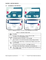
Displays for Traveler, Scout SE, Carat & Gold Series (TAJ and TAG) .................1-6
1-5
Traveler Display Indicators....................................................................................1-7
1-6
RS232 Interface (PN 71147376 or 72206287)......................................................1-9
1-7
The RS232 Interface connects to the scale through the Bottom Housing.............1-9
3-1
Scale Bottom, with three screws that secure the Housing shown.........................3-1
3-2
Printed Circuit Board and Display .........................................................................3-2
3-3
Auxiliary Display, with top off.................................................................................3-3
4-1
Segment
Display ...................................................................................................4-1
4-2
Scale drawing of Traveler Load Cell and Weighing Pan .......................................4-5
5-1
Traveler Scales with Square Draft Shield: Housing & Parts..................................5-2
5-2
Traveler 203 with Round Draft Shield: Housing & Parts .......................................5-4
5-3
Traveler Scales with No Draft Shield: Housing & Parts.........................................5-6
C-1
The RS232 Interface connects to the scale through the Bottom Housing............ C-1
C-2
RS232 Interface (PN 71147376 or 72206287)..................................................... C-1
C-2
Com Port Configuration screen with default settings ........................................... C-2
C-3
Config Tool’s Test Command screen ................................................................... C-2
C-4
Config Tool’s Configuration Screen...................................................................... C-3
Traveler™ Series Scales: Service Manual
ii
Ohaus Corporation www.ohaus.com
Содержание TA152
Страница 2: ......
Страница 4: ......
Страница 5: ......
Страница 23: ...CHAPTER 3 MAINTENANCE PROCEDURES Ohaus Corporation www ohaus com 3 4 Traveler Series Service Manual...
Страница 37: ...CHAPTER 5 PARTS LISTS DIAGRAMS Ohaus Corporation www ohaus com 5 8 Traveler Series Service Manual...
Страница 39: ...APPENDIX A STANDARD CALIBRATION Ohaus Corporation www ohaus com A 2 Traveler Series Service Manual...
Страница 43: ...APPENDIX B THE SERVICE MENU Ohaus Corporation www ohaus com B 4 Traveler Series Service Manual...
Страница 48: ......
Страница 49: ...80251719 P N 80251719 SERVICE MANUAL TRAVELER SERIES SCALES...


