25 - 97
Instruction Manual
AC 02/2019-rev.1.1
3.3.6 SCARICO CONDENSA (motori
raffreddati a liquido)
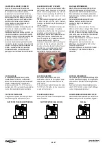
I motori sono provvisti di fori (M6 o M8) per lo
scarico della condensa realizzati nella parte
inferiore della carcassa motore.
Per mantenere inalterato il grado di protezione
dei motori è necessario collegare questi fori ai
tubi di scarico condensa.
3.3.6 CONDENSATION EXHAUST (liquid
cooled motors)
The motors are provided with holes (M6 or M8)
for the condensation exhaust. The holes are
located on the bottom side of the motor frame.
In order tokeep the motor protection degree it is
necessary to connect these holes to the exhaust
pipes.
3.3.6 KONDENSATABLAUF (wassergekühlte
Motoren)
Die Motore sind mit einer Kondensat Ablaufbohrung
versehen (M6 oder M8), die sich unten am
Motorgehäuse befinden. Um die Motorschutzart zu
erhalten, müssen diese Bohrungen an einen
Schlauch angeschlossen werden für den Kondensat
Ablauf.
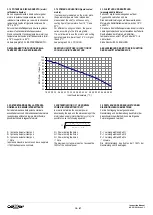
3.3.7 SISTEMI DI RAFFREDDAMENTO (motori
raffreddati a liquido)
Per mantenere costante ed entro i limiti stabiliti la
temperatura del liquido di raffreddamento in ingresso
al motore, è necessario un sistema esterno che
controlli e regoli la temperatura.
Raccomandiamo l’utilizzo di un sistema a ci
rcuito
chiuso dotato di pompa di ricircolo acqua e
termostato di regolazione (Chiller).
E’ composto da
un sistema completo di compressore, radiatore,
pompa, elettroventilatore e termostato. Mantiene la
temperatura del liquido di raffreddamento costante
indipendentemente dalla temperatura ambiente.
3.3.7 COOLING SYSTEMS (liquid cooled
motors)
For maintaining the level constant and within
stabilised limits, the temperature of the coolant at the
motor intake must be controlled and regulated by an
external system.
We raccomand to use a closed circuit cooling system
provided with pump and temperature control device
(Chiller). This unit consists of a system with the
following components: Compressor, Radiator, Pump,
Electric fan and Thermostat. It maintains the coolant
temperature constant independently from the
ambient temperature.
3.3.5 KÜHLSYSTEME (wassergekühlte
Motoren)
Um die Temperatur des Kühlmittels im Eingang
innerhalb der festgelegten Werte zu halten, ist
es notwendig ein externes System zur
Konstanthaltung der Temperatur zu installieren.
Wir empfehlen ein geschlossenenes System mit
Wasser Umlauf-pumpe und Thermostat (Chiller).
Besteht aus folgenden Komponenten:
Kompressor, Wärmetauscher, Pumpe,
elektrischer Lüfter und Thermostat. Hält die
Kühlmittel-temperatur unabhängig von der
Umgebungs-temperatur konstant.
3.4 RUMOROSITÀ
Il livello di rumorosità dei motori rientra nei limiti
imposti dalle norme IEC 60034-9 ed il valore rilevato
viene indicato come livello di pressione sonora L
WA
espresso in dB(A).
La rumorosità dei motori elettrici deriva
essenzialmente da fattori fluidodinamici,
elettromagnetici e meccanici.
Il movimento veloce dell’aria aspirata e messa in
movimento dall’elettroventilatore è sicuramente la
fonte principale di rumore udibile durante il
funzionamento del motore. In particolar modo la
pressione sonora più evidente si riscontra in
prossimità della bocca di aspirazione del ventilatore e
nelle vicinanze delle fessure di scarico dell’aria calda.
Gli effetti elettromagnetici e meccanici producono a
loro volta una certa rumorosità comunque inferiore a
quella dovuta alla ventilazione.
La misurazione della rumorosità avviene in ambiente
a bassa riflessione con rilevamento in tutte le
direzioni ad 1m di distanza dalla sorgente e con
motore funzionante tramite alimentazione
sinusoidale.
La rumorosità del motore può variare anche
sensibilmente in funzione del tipo di drive che lo
alimenta e della struttura a cui è fissato.
Le rilevazioni sono effettuate con metodo a
sospensione libera. In alcuni casi la rumorosità
elettromagnetica del motore potrebbe aumentare
considerevolmente in presenza di particolari
frequenze critiche (risonanze). Queste frequenze
hanno un range molto ristretto ed è pertanto
necessario “saltare” queste frequenze di lavoro
(skip frequency) per ottenere un funzionamento
silenzioso. Durante la rilevazione della
rumorosità del motore queste frequenze non
vengono considerate.
3.4 NOISE LEVEL
The noise level of the motors is within the limits
of IEC 60034-9 standards, and the measurement
taken is indicated as the noise level pressure L
WA
in dB(A).
The noise level of an electric motor depends
essentially on fluid-dynamic, electromagnetic and
mechanical factors.
The fast movement of the air sucked and blown
by the electric fan onto the motor is certainly the
main audible noise source when an electric motor
is under operation.
In particular, the highest noise level pressure is
measured near the electric fan intake hole and
near the air outlets used to evacuate the hot air.
Electromagnetic and mechanical effects also
produce noise, but of a lower level than the fan.
Noise is measured in an environment with a low
level of reflection, taking readings in all directions
at a distance of 1m from the noise source and
with the motor powered by a sinusoidal source.
The noise level of a motor can vary considerably
on the basis of the type of drive (inverter)
connected to the motor and the structure on
which it is installed.
Readings are taken using the free-hanging
method. In some cases the electromagnetic
noise of the motor can increase considerably
at particularly critical supply frequencies
(resonance). These frequencies have a very
small range so we recommend “skipping”
these frequencies for silent and low noise
operatrion.
When the noise level of a motor is measured,
these frequencies are not taken into
consideration.
3.4 GERÄUSCHPEGEL
Der Geräuschpegel der Motoren liegt innerhalb der
von Norm IEC 60034-9 festgelegten Grenzwerte.
Der ermittelte Wert ist als Schalldruckpegel L
WA
in
dB(A) angegeben.
Die Geräuschentwicklung der Elektromotoren
beruht im Wesentlichen auf hydrodynamischen,
elektromagnetischen und mechanischen Faktoren.
Das schnelle Strömen der angesaugten und vom
Elektrolüfter umgewälzten Luft ist sicherlich die
Hauptursache dafür, dass während des
Elektromotorbetriebs Geräusche zu hören sind. Der
Schalldruck ist insbesondere in der Nähe des
Lüftersaugmunds und der Entlüftungsschlitze am
deutlichsten.
Die elektromagnetischen und mechanischen
Effekte erzeugen ihrerseits auch einen gewissen
Geräuschpegel, der allerdings geringer als der
durch die Lüftung erzeugte ist.
Der Geräuschpegel wird in einem reflexionsarmen
Raum und bei mit sinusförmiger Speisespannung
betriebenem Motor gemessen. Die Erfassung
erfolgt dabei aus allen Richtungen in 1 m Abstand
von der Quelle.
Der Geräuschpegel des Motors kann auch je nach
vorgeschaltetem Antrieb und nach verwendeter
Grundkonstruktion stark variieren. Die Messungen
erfolgen bei frei aufgehängtem Motor. In einigen
Fällen könnte sich die elektromagnetische
Geräuschentwicklung des Motors beim Vorliegen
spezieller kritischer Frequenzen erhöhen
(Resonanzen). Diese Frequenzen haben ein
äußerst enges Feld. Für einen leisen Betrieb
müssen diese Arbeitsfrequenzen daher
„übersprungen“ werden (skip freq
uency). Diese
Frequenzen werden bei Messung des
Motorgeräuschpegels nicht berücksichtigt.
Содержание HQCA
Страница 2: ...2 97 Instruction Manual AC 02 2019 rev 1 1...

