42 - 97
Instruction Manual
AC 02/2019-rev.1.1
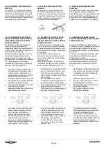
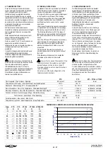
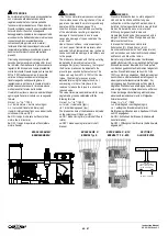
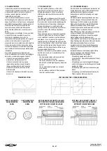
5.2 TRASDUTTORE (ENCODER)
A richiesta i motori possono essere forniti
completi di trasduttore di velocità/posizione
(encoder) installato nella parte posteriore del
motore.
Normalmente è utilizzato un trasduttore specifico
per motori elettrici costruito ad albero cavo per
ridurre le dimensioni d’ingombro e garant
ire una
perfetta connessione meccanica con l’albero del
motore.
Il corpo del trasduttore è fissato al coperchio
posteriore del motore ed è reso oscillante per
mezzo di un braccio di reazione che ha il compito
di assorbire eventuali disallineamenti assiali e
radiali e non esercitare carichi sui cuscinetti
dell’encoder.
Modelli speciali con esecuzione meccanica ad albero
spo giunto di trasmissione oppure con foro
passante di grosso diametro sono disponibili a
richiesta. Per la connessione elettrica è utilizzato un
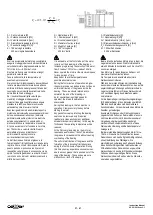
connettore maschio (da pannello), del tipo a 10 pins
cablato secondo il nostro standard.
La parte femmina (volante) con contatti a saldare è
fornita con il motore.
Assicurarsi sempre che i dati elettrici del trasduttore
siano compatibili co
n quelli dell’inverter che alimenta
il motore, che la tensione di alimentazione sia
corretta e che i collegamenti siano rispettati.
Non alimentare i canali di uscita del trasduttore e non
fare mai funzionare il motore se il trasduttore ha i cavi
di uscita in cortocircuito tra loro o verso massa. Non
effettuare la prova di alta tensione sui terminali del
trasduttore. Gia scritto sopra
Usare sempre cavo scermato per il collegamento
con l’inverter.
Durante la fase di saldatura non surriscaldare
eccessivamente i contatti del connettore. Evitare che
gocce di saldatura cortocircuitino i contatti del
connettore. Il mancato rispetto di una delle
sopracitate avvertenze potrebbe comportare
l’immediata rottura dell’encoder.
Altri modelli con elettroniche speciali (sinusoidali,
assoluti etc.) potrebbero essere provvisti di
connettore diverso. In questo caso lo schema di
connessione sarà inserito all’interno della scatola
morsetti. Normalmente la velocità massima
meccanica di rotazione dell’encoder è limitata a
8.000rpm
–
non superare questo limite per evitare
danni al trasduttore.
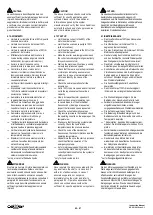
I motori della serie LTS / LTS-TB possono avere
l’encoder collegato all’albero motore tramite un rinvio
con cinghia e puleggia. Il rapporto di trasmissione è
1:4 (nr.1 giro albero motore corrisponde a 4 giri
albero encoder).
Solo per la grandezza LTS / LTS-TB 355 il rapporto
di trasmissione è 1:3.
Questo rapporto di trasmissione deve essere
considerato per la corretta taratura del drive.
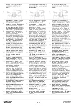
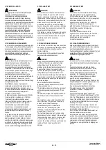
5.2 TRANSDUCER (ENCODER)
On request the motors can be supplied with
speed/position transducer (encoder) installed at
the rear side of the motor.
Normally a specific hollow shaft transducer
expecially made for electric motors is used to
reduce the overall dimensions (motor length) and
guarantee perfect mechanical coupling with the
shaft.
The body of the transducer is mechanically fixed
to the rear cover of the motor and can oscillate
thanks to a flexible reaction arm which absorbs
possible axial and radial misalignment and do not
create any load the shaft and the bearings of the
encoder.
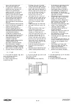
Special models with a protruding shaft +
transmission coupling or large diameter through
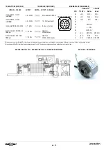
hole, are available on request. Our standard male
connector (panel type), with 10 pins is used for
the electrical connection of the encoder and is
wired in accordance to our standard diagram
shown below.
The female side (free) with contacts to solder, is
supplied as standard with the motor.
Always be sure that the electrical data of the
transducer be compatible with those of the
inverter feeding the motor, that the supply voltage
is correct and that the connections are correctly
laid out.
Do not feed the transducer’s outlet channels and
do not operate the motor if the transducer has the
outlet wires short-circuited between them or with
ground. Do not carry out the high voltage test on
the transducer terminal. Always use shielded
cables for the connection with the inverter.
During the welding phase do not overheat the
connector contacts. Avoid short-circuiting the
connector’s contacts with
welding drops. Lack of
respect for any one of the preceding notices
could cause the immediate failure of the encoder.
Other models with special electronics (sinusoidal,
absolute, etc.) could be equipped with different
connectors. In this case the connection
schematics is inserted in the terminal board box.
Normally, the maximum mechanical rotating
speed of the encoder is limited to 8000 rpm’s
- do
not exceed this limit to avoid damaging the
transducer.
The LTS / LTS-TB motors may have the encoder
connected to the shaft
through a transmission
belt and pulley. The gear ratio is 1:4 (No.1 motor
complete shaft revolution corresponds to 4 turns
of the encoder shaft).
Only for the LTS / LTS-TB 355 frame size the
transmission ratio is 1:3.
This transmission ratio must be considered for
the proper drive set-up.
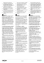
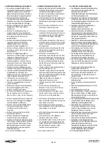
5.2 MESSWERTGEBER (ENCODER)
Die Motoren können auf Anfrage mit einem Dreh-
geber (Encoder) an der Motorrückseite geliefert
werden.
In der Regel wird ein speziell für Elektromotoren
entwickelter Messwertgeber eingesetzt, der zur
Verringerung der Außenmaße und zur
Gewährleistung des einwandfreien mechanischen
Anschlusses an die Antriebswelle mit einer
Hohlwelle ausgerüstet ist.
Das Gebergehäuse ist an der hinteren
Motorabdeckung über eine Drehmomentstütze
schwingend angebracht, um etwaige axiale und
radiale Ausrichtungsfehler auszugleichen und
Belastungen des Drehgeber-Lagers zu
vermeiden.
Sondermodelle mit Vollwelle und Kupplung bzw.
mit großer Durchgangsbohrung sind auf Anfrage
verfügbar. Für den Elektroanschluss wird ein
nach unseren Standards verkabelter 10-poliger
Stift Stecker verwendet.
Der entsprechende Gegenstecker (Buchse) mit
Lötkontakten ist serienmäßig im Lieferumfang des
Motors enthalten.
Immer beachten, dass die elektrischen Daten der
Messwertgeber mit dem Umrichter kompatibel sind,
der den Motor speist, Versorgungsspannung und
Anschlüsse korrekt sind.
Nie die Signalkanäle der Messwertgeber speisen
oder den Motor laufen lassen wenn die Kabel im
Ausgang kurzgeschlossen oder geerdet sind.
Immer ein geschirmtes Kabel für den Anschluss am
Umrichter benutzen.
Während des Lötens darauf achten die Kontakte
des Steckers nicht zu überhitzen und keine Tropfen
produzieren, die Kurzschluss der Kontakte
provozieren könnten. Ein Nichtbeachten obiger
Warnungen könnte zum sofortigen Ausfall des
Drehgebers führen.
Andere Ausführungen mit spezieller
Auswertelektronik (Sinus, Absolutwertgeber)
könnten mit einem unterschiedlichen Stecker
ausgerüstet sein.
In diesem Fall befindet sich das Anschlussschema
beigelegt im Klemmenkasten.
Im Normalfall ist der Drehzahl der Drehgeber auf
8000 1/min begrenzt- niemals diesen Grenzwert
überschreiten um die Beschädigungen des
Drehgebers zu vermeiden.
Motoren der Serie LTS / LTS-TB können Drehgeber
aufweisen, die über einen Riementrieb angetrieben
werden. Die Übersetzung beträgt 1:4 (1 Motor-
wellenumdrehung auf 4 Drehgeberumdrehungen).
Nur für die Baugrösse LTS / LTS-TB 355 beträgt
die Übersetzung 1:3.
Diese Übersetzungen müssen für die Einstellung
des Umrichters beachtet werden.
Содержание HQCA
Страница 2: ...2 97 Instruction Manual AC 02 2019 rev 1 1...


