5.
ASSEMBLING
5.1
Installation
5.1.1
To identify the best installation position consider the
max. application limits and NPSH values.
➣
scheme 5.
5.1.2
Consider the environmental conditions.
Influence of temperature, moisture and explosive at-
mosphere can affect function, security and life time of
the pump.
5.1.3
When locating the unit ensure that it can be worked
on easily as you will need to maintain it.
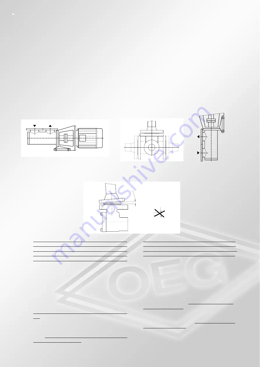
5.1.4 Assembling Position/Flow Direction:
➣
scheme 12
5.2
Pipework Connection
Avoid stress of pipes
➣
scheme 13
.
The pumps should not serve as a fixed reference po-
int for the installed pipe line. Such occurences should
be avoided, if possible, e. g. bracing, the expansion of
pipe due to variations in temperature and unit stress.
We recommend to install a compensator in case of
heat expansions of the pipes. The dimensions of the
suction pipe must allow a liquid velocity of 0,5 up to
max. 1,3 m/sec and the pressure pipe must allow a li-
quid velocity of 2 - 3 m/sec. The suction pipework
must be installed with a gradual rise and air-tight. The
pipework and the pump must be free of impurity (e.g.
flushing). When the pipework installation is being te-
sted for leaks pay attention to the max. admissible in-
let pressure of shaft seal. Attention: don«t use water
cause of rust formation. When draining the system it
is important that pipe and pump are free from dirt (e.
g. welding beads, pieces of steal etc). Carry out pre-
servation (see Preservation). Oxydation and impurity
can cause a breakdown.
5.
MONTAGE
5.1
Aufstellung
5.1.1
Bei der Standortwahl sind die Einsatzgrenzen und
NPSH-Werte zu beachten.
➣
Bild 5
5.1.2
Es sind die Umgebungsbedingungen zu beachten.
Funktion, Sicherheit und Lebensdauer dŸrfen nicht
durch Feuchtigkeit, TemperatureinflŸsse oder explo-
sionsfŠhige AthmosphŠren beeintrŠchtigt werden.
5.1.3
Beim Aufstellen ist darauf zu achten, da§ alle Teile
der Pumpe gut zugŠnglich sind, und eine Wartung
leicht mšglich ist.
5.1.4 Einbaulage / Durchflu§richtungen
➣
Bild 12
5.2
Rohrleitungsanschlu§
Rohrspannungen vermeiden
➣
Bild 13.
GrundsŠtzlich dŸrfen die Pumpen nicht als Fixpunkt
der angeschlossenen Rohrleitungen dienen. Even-
tuell auftretende KrŠfte und Momente (z.B.: Verspan-
nungen, Ausdehnungen der Rohrleitung durch Tem-
peratureinflŸsse, ReaktionskrŠfte) sind zu vermeiden.
Bei mšglichen WŠrmeausdehnungen der Rohrleitun-
gen ist der Einbau von Kompensatoren zu empfehlen.
Die Saugleitung ist so zu bemessen, da§ die Flie§ge-
schwindigkeit zwischen 0,5 bis max. 1,3 m/sec. und
die Druckleitung zwischen 2 bis 3 m/sec. liegt. Die
Saugleitung mu§ vakuumdicht und steigend verlegt
werden. Rohrsystem und Pumpe mŸssen frei von
Verunreinigungen sein (z.B.: SpŸlung). Wird das
Rohrsystem auf Dichtheit geprŸft, ist der max. zulŠs-
sige Zulaufdruck der Wellendichtung zu beachten.
Achtung: wegen Rostbildung kein Wasser verwen-
den. Beim Entleeren der FlŸssigkeit ist darauf zu
achten, da§ die Rohrleitung und die Pumpe frei von
Verunreinigungen sind (z.B.: Schwei§schlacke, Zun-
der). Konservierung vornehmen (siehe Konservie-
rung). Oxydation und Verunreinigungen kšnnen zu ei-
nem Pumpenausfall fŸhren.
- 7 -
Содержание N Series
Страница 15: ......


