NXP Semiconductors
UM11603
RDGD31603PHSEVM three-phase inverter reference design
Name
Function
VCCHU
High-side phase U VCC voltage test point
Isolated positive voltage supply (15 V to 18 V)
VCCHV
High-side phase V VCC voltage test point
Isolated positive voltage supply (15 V to 18 V)
VCCHW
High-side phase W VCC voltage test point
Isolated positive voltage supply (15 V to 18 V)
VCCLU
Low-side phase U VCC voltage test point
Isolated positive voltage supply (15 V to 18 V)
VCCLV
Low-side phase V VCC voltage test point
Isolated positive voltage supply (15 V to 18 V)
VCCLW
Low-side phase W VCC voltage test point
Isolated positive voltage supply (15 V to 18 V)
VPWR
+12 V DC VPWR low voltage positive supply connection (+12 V DC)
VPWR GND
VPWR low voltage supply ground connection (GND1)
Table 5. Power supply test point descriptions
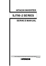
4.2.7 Gate drive resistors
•
RGH - RGH - gate high resistor in series with the GH pin at the output of the GD3100
high-side driver and IGBT gate that controls the turn on current for IGBT/SiC gate.
•
RGL - gate low resistor in series with the GL pin at the output of the GD3100 low-side
driver and IGBT gate that controls the turn off current for IGBT/SiC gate.
•
RAMC - series resistor between IGBT/SiC gate and AMC input pin of the GD3100 high-
side/low-side driver for gate sensing and Active Miller clamping.
Figure 7. Gate drive resistors for each phase high-side and low-side
UM11063
All information provided in this document is subject to legal disclaimers.
© NXP B.V. 2021. All rights reserved.
User manual
Rev. 1 — 18 August 2021
13 / 40