NXP Semiconductors RDAIRBAGPSI5 Скачать руководство пользователя страница 40

RDAIRPABPSI5UG , Rev. 2.0

40

Freescale Semiconductor, Inc.

Schematics

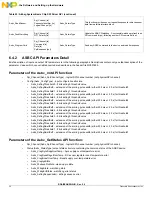
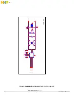
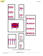
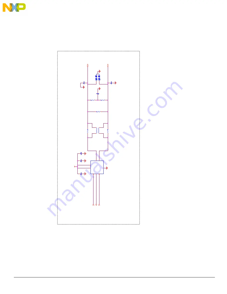
Figure 21. Evaluation Board Schematic Part 2 - CAN High Speed I/F

CAN HS

VC

C

_

5V

MCU_

C

A

N

TX

Page[

3

]

MCU_

C

A

N

RX

Page[

3

]

M

C

U

_C

AN

_ST

B

Y

Page[

3

]

C

A

N

H

Page[

5

]

C

A

N

L

Page[

5

]

C4

1

47PF

DNP

R3

9

120

C4

0

10nF

DNP

C3

7

0.

1U

F

C3

9

47PF

DNP

D8

PESD

1

C

A

N

DNP

1

2

3

R4

1

0

R3

8

60.

4

DNP

R4

0

60.

4

DNP

R3

7

0

L1

100 uH

DNP

1

3

2

4

U9

M

C

33901W

EF

GND

2

TX

D

1

RX

D

4

ST

B

8

CA

NH

7

CA

NL

6

VDD

3

VIO

5

C3

6

1uF

C3

8

1uF

Содержание RDAIRBAGPSI5

Страница 1: ...Freescale Semiconductor Inc 2014 All rights reserved Freescale Semiconductor User s Guide Document Number RDAIRBAGPSI5UG Rev 2 0 10 2014 RDAIRBAGPSI5 Airbag Reference Platform Figure 1 RDAIRBAGPSI5...

Страница 2: ...Notice 3 2 Getting Started 4 3 Understanding the System 6 4 Getting to know the Hardware 10 5 Describing the Device Functions 14 6 Installing the Software and Setting up the Hardware 19 7 Schematics...

Страница 3: ...ale reserves the right to make changes without further notice to any products herein Freescale makes no warranty representation or guarantee regarding the suitability of its products for any particula...

Страница 4: ...ng proven high volume SMARTMOS mixed signal technology and system in package devices utilizing power SMARTMOS and MCU dies Freescale products enable longer battery life smaller form factor component c...

Страница 5: ...orm FreeMASTER GUI Application http www freescale com arp USB FTDI cable Reference TTL 232R 5V All software tools can be downloaded under Software Tools tab of the RDAIRBAGPSI5 webpage Registration mi...

Страница 6: ...elt sensors and vehicle communications networks and ECU functions including full power supply architecture and a local mid g X Y safing sensor are also supported The new ARP hardware is implemented us...

Страница 7: ...p to 512 KB flash MC33789 Airbag System Basis Chip PSI5 Power supply for complete ECU Up to four Satellite Sensor interfaces PSI5 Up to nine configurable switch input monitors for simple switch resist...

Страница 8: ...is exceeded in three consecutive acquisition cycles the system is armed by enabling the safing outputs which in turn enables the squib drivers so that the application can fire the necessary squibs bas...

Страница 9: ...squibs 3 3 MC33797 Four Channel Squib Driver Each channel consists of a high side and a low side switch The ARP uses two MC33797 devices connected in cross coupled mode i e high side switch from one d...

Страница 10: ...MMA68xx Central Accelerometer also called Local Safing Sensor designed for use in automotive airbag systems CAN HS Transceiver MC33901 Physical interface between the CAN protocol controller of an MCU...

Страница 11: ...lication mode LED color Red 4 LED D4 first indicates MC33797 are correctly initialized only during INIT phase Then it is used to display Front Driver deployment during GUI Application mode LED color R...

Страница 12: ...itor for DC sensor 7 OUT2_S Source pin of configurable output FET 2 23 CANH CAN Bus High Signal 8 OUT2_D Drain pin of configurable output FET 2 24 CANL CAN Bus Low Signal 9 OUT1_D Drain pin of configu...

Страница 13: ...quib Driver Low side switch 6 48 NC Not Connected 37 HI_7 Source of the Squib Driver High side switch 7 49 PSI5_1OUT PSI5 Channel1 Signal line 38 LO_7 Drain of the Squib Driver Low side switch 7 50 PS...

Страница 14: ...is turned on the large energy reserve capacitor min 2200 F will be charged 5 1 2 Power Supply Energy Reserve Capacitor ESR Diagnostic During ESR diagnostic the energy reserve capacitor is slightly dis...

Страница 15: ...ip and whenever the microcontroller reads a sensor value the response from the sensor or system basis chip is recognized as being sensor data and is automatically read into the safing block The only r...

Страница 16: ...etting is the most common configuration A special mode exists which allows the Manchester encoded data from a satellite sensor to be monitored on the LIN RXD output pin for example in case MCU has a P...

Страница 17: ...the ENDINIT bit is set and this locks out access to the configuration registers 5 2 2 Configuration Axis Operation The axis operation configuration triggers self test and selects one of the low pass f...

Страница 18: ...on possible is the time the device remains enabled after the fire enable FEN1 FEN2 pins have been activated This is equivalent to the arming pulse stretch time applied to the safing output on both the...

Страница 19: ...t removes details of working with a MPC560xP 32 bit microcontroller This will allow a developer to focus attention on the application tasks instead of focusing on the very specific functionality of th...

Страница 20: ...f the FreeMASTER driver API functions This should be included in the application using include directive wherever there is need to call any of the FreeMASTER driver API functions The FreeMASTER driver...

Страница 21: ...m central and satellite accelerometers These numerical values are displayed in points where sensors should be placed inside the car View acceleration data plotted on a graph which allows informative o...

Страница 22: ...on values Front Satellites Central Accel above the threshold is required to simulate front deployment Other deployment indicators can be found on the actual ARP Hardware Four red color LEDs are implem...

Страница 23: ...Software and Setting up the Hardware 6 2 6 Configuring the Hardware using FreeMASTER Figure 11 RDAIRBAGPSI5 Configured for ARP Evaluation Using FreeMASTER GUI Figure 12 RDAIRBAGPSI5 1 Configured for...

Страница 24: ...Hardware four red LEDs should turn on one after another then they all turn off This firmware sequence is intended to provide visual information to the user that all four main devices MC33789 MMA68xx M...

Страница 25: ...blish the connection See Figure 14 Figure 14 ARP Graphical User Interface File Start At the bottom of the GUI screen a message Communication With Reference Board Works Properly should appear Once the...

Страница 26: ...sources could be The ARP demo has no power Check the power supply setup COM ports are not assigned correctly On the PC desktop right click on My computer and select Properties The System Properties wi...

Страница 27: ...Software code using CodeWarrior to download a customized firmware The following sections describe all steps required to configure RDAIRBAGPSI5 for MCU Software development 6 3 1 Installing CodeWarrio...

Страница 28: ...Multilink which provides an easy to use debug and programming interface for Freescale s Power Architecture MPC5xx line of microprocessors This accessory will be needed to flash the MCU using Freescale...

Страница 29: ...ses are reported via this service Asbc_SetAnlMuxSource Spi_Channel in Source in Asbc_ReturnType Allow to change the analog parameter which is connected to the AOUT output Asbc_SetDcsMuxSource Spi_Chan...

Страница 30: ...Asbc_SafingDwellExt5 extension of the arming pulse width either 255 ms or 2 0 s for threshold5 Asbc_SafingThreshold6 8 bits safing 6 threshold value Asbc_SafingDwellExt6 extension of the arming pulse...

Страница 31: ...nableType input parameter safing test enable SafingLevel Asbc_SafingLevelType input parameter arming output level Parameters of the Asbc_SetVregMode API function Spi_Channel Asbc_SpiChannelType logica...

Страница 32: ...4 enable disable Asbc_PSI5Chann4SynPuls Asbc_PSI5Chann4SynPulsType PSI5 channel 4 sync pulse enable disable Parameters of the Asbc_GetPsi5Status API function Spi_Channel Asbc_SpiChannelType logical SP...

Страница 33: ...rity Asbc_WdLevelType watchdog polarity value Parameters of the Asbc_ProgramCmd API function Spi_Channel Asbc_SpiChannelType logical SPI channel number not physical SPI channel Command Asbc_SpiChannel...

Страница 34: ...negative arming window size definitions meaning depend on the state of the Acc_ArmOutput variable Acc_YArm_NegWinSize Y axis negative arming window size definitions meaning depend on the state of the...

Страница 35: ...window size definitions or arming count limit definitions function depending on the state of the Acc_ArmOutput variable Acc_YArm_PosWin_CountLimit Y axis positive arming window size definitions or arm...

Страница 36: ...and 6 6 SQUIB Driver The SQUIB driver is created as a separate software module The main advantage is full HW abstraction and API independence used in the MCU family The driver API covers the entire fu...

Страница 37: ...the VDIAG_1 pin Squib_Stat1HSSafingSens High side Safing sensor diagnostics monitors the VFIRE_XX pin connection to the VDIAG_1 pin Squib_Stat2VdiagResult firing supply voltage VDIAG_2 diagnostics vol...

Страница 38: ...tance on the VFIRE_RTN1 pin for open pin connections Squib_StatVfireRtn2 reports the resistance on the VFIRE_RTN2 pin for open pin connections Squib_Stat1AResistance Squib 1A resistance value Squib_St...

Страница 39: ...N0_TXD SSCM_DEBUG2 EIRQ17 79 B3 GPIO19 SSCM_DEBUG3 LIN0_RXD 80 B6 GPIO22 CONTROL_CLKOUT DSPI2_CS2 EIRQ18 96 B7 GPIO23 ADC0_AN0 LIN0_RXD 29 B8 GPIO24 ADC0_AN1 ETIMER0_ETC5 31 B9 GPIO25 ADC0_AN11 35 B10...

Страница 40: ...peed I F CAN HS VCC_5V MCU_CANTX Page 3 MCU_CANRX Page 3 MCU_CAN_STBY Page 3 CANH Page 5 CANL Page 5 C41 47PF DNP R39 120 C40 10nF DNP C37 0 1UF C39 47PF DNP D8 PESD1CAN DNP 1 2 3 R41 0 R38 60 4 DNP R...

Страница 41: ...T1_S Page 6 OUT2_S Page 6 OUT1_D Page 6 OUT2_D Page 6 IN1 Page 6 IN2 Page 6 IN3 Page 6 IN4 Page 6 IN5 Page 6 IN6 Page 6 IN7 Page 6 IN8 Page 6 IN9 Page 6 HI_1 Page 7 HI_3 Page 7 HI_2 Page 7 HI_4 Page 7...

Страница 42: ...8 MCU_LINRX Page 3 MCU_LINTX Page 3 LIN Page 5 C92 47uF UUD1E470MCL1GS 25V C77 220uF EPCOS B41142A7227M000 C90 1uF C0805C105K4RAC U3 MC33789 ASST 1 CS_C 2 CS_B 3 CS_A 4 SCRAP 5 PSI5_1 6 PSI5_2 7 PSI5_...

Страница 43: ...e 5 HI_3 Page 5 HI_4 Page 5 LO_1 Page 5 LO_2 Page 5 LO_3 Page 5 LO_4 Page 5 DSPI_1_SO Page 3 LO_5 Page 5 LO_6 Page 5 LO_7 Page 5 LO_8 Page 5 HI_5 Page 5 HI_6 Page 5 HI_7 Page 5 HI_8 Page 5 U5 MC33797B...

Страница 44: ...ge 3 6 8 DSPI_0_CS2 Page 3 FSLACC_Y_ST Page 3 FSLACC_R_STATUS Page 3 FSLACC_R_VOUT Page 6 FSLACC_R_ST Page 3 6 C105 1uF R66 10K C110 0 1UF C106 1uF U7 MMA6900KQ CREF1 1 CREF2 2 VCC 3 VSS 4 DOUT 5 SCLK...

Страница 45: ...RDAIRPABPSI5UG Rev 2 0 Freescale Semiconductor 45 Board Layout 8 Board Layout 8 1 Assembly Layer Top...

Страница 46: ...SO8 3 Crystal Oscillators 1 Y1 8 MHz NX5032GA 8 000M NDK XTAL 8 MHz SMD 3 Transistors 1 Q1 NPN BCP68T1G TRAN NPN PWR 20 V 1 A SOT 223 3 1 Q2 PNP BCP53 16T1G TRAN PNP GEN 1 5 A 80 V SOT 223 3 LEDs 1 D1...

Страница 47: ...1210 CC1210 4 C20 C22 C24 C26 10 uF 3216 18 CAP TANT 10 UF 16 V 10 CC3216 4 C21 C23 C25 C27 0 22 uF CAP CER 0 22 UF 6 3 V 20 X5R 0402 0402_CC 2 C39 C41 47 pF CAP CER 47 PF 50 V 5 C0G 0603 CC0603 2 1...

Страница 48: ...A 5p3_7p5x8p3 3 1 L5 68 uH B82475M1683K000 Epcos IND PWR 68 UH 100 KHZ 1 11 A 10x10p4 3 Resistors 7 R1 R31 R32 R33 R34 R35 R36 1 KOhm CRCW04021K00JNED RES MF 1 0 K 1 16 W 5 0402 0402_CC 1 R2 1 5 KOhm...

Страница 49: ...0 MA 12 V SMT SMD 7 TP1 TP2 TP3 TP4 TP5 TP6 TP7 TPAD_050 TEST POINT PAD 50MIL DIA NOT A COMPONENT TPAD_050 1 JP1 HDR 1X6 TSW 106 07 S S HDR 1X6 TH 100MIL SP 330 H 1 J1 HDR_2X7 TSW 107 07 S D HDR 2X7 T...

Страница 50: ...prod_summary jsp code MC33789 MMA68xxKW Product Summary Page http www freescale com webapp sps site prod_summary jsp code MMA68xxKW MC33797 Product Summary Page http www freescale com webapp sps site...

Страница 51: ...ion History Revision Date Description of Changes 1 0 8 2014 Initial Release 2 0 10 2014 Added kit contents for RDAIRBAGPSI5 1 Updated Required Equipment section Added Figure 12 configuration diagram f...

Страница 52: ...on consequential or incidental damages Typical parameters that may be provided in Freescale data sheets and or specifications can and do vary in different applications and actual performance may vary...

Страница 53: ...Mouser Electronics Authorized Distributor Click to View Pricing Inventory Delivery Lifecycle Information NXP RDAIRBAGPSI5 1 RDAIRBAGPSI5...

Отзывы: