


RDAIRPABPSI5UG , Rev. 2.0
Freescale Semiconductor
11
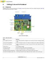
Getting to know the Hardware
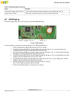
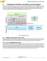
4.2 LED Display
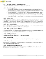
This section describes the LEDs on the lower portion of the RDAIRBAGPSI5 board.
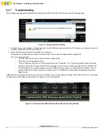
Figure 4. LED Locations
The following LEDs are provided as visual output devices for the RDAIRBAGPSI5 board:
1.
LED D1 indicates when a System Reset occurred (LED color: Yellow).
2.
LED D2 first indicates MC33789 is correctly initialized only during INIT phase. Then, it is used to display Front
Passenger deployment during GUI Application mode (LED color: Red).
3.
LED D3 first indicates MMA68xx is correctly initialized only during INIT phase. Then, it is used to display Rear Right
Side deployment during GUI Application mode (LED color: Red).
4.
LED D4 first indicates MC33797 are correctly initialized only during INIT phase. Then, it is used to display Front Driver
deployment during GUI Application mode (LED color: Red).
5.
LED D5 first indicates MCU is correctly initialized only during INIT phase. Then, it is used to display Rear Left Side
deployment during GUI Application mode (LED color: Red).
6.
LED D6 indicates when a FCU fault is detected by MCU (LED color: Orange).
Note: If no FCU faults are detected, LED is turned ON.
7.
LED D7 indicates MCU Software is running (LED color: Green).
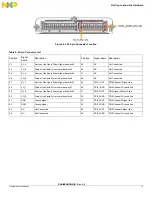
On-Board Side Airbags Deployment LEDs
2x LEDs used to indicate a side impact Deployment event: Rear Right and/or Rear Left
Energy Reserve Capacitor
Autarky Capacitor used as Energy Reserve in case of Battery disconnection
Table 2. Board Description (continued)
Name
Definition
REDD2,3,4,5
OrangeD6 GreenD7
YellowD1