


RDAIRPABPSI5UG , Rev. 2.0
20
Freescale Semiconductor, Inc.
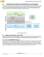
Installing the Software and Setting up the Hardware
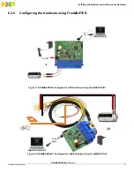
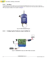
6.2.1
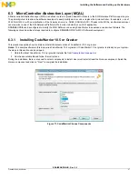
Installing FreeMASTER on your Computer
To set up the GUI on your PC, you have to install the FreeMASTER software if not already installed.
Notes:
If FreeMASTER is already on your system, the steps in this section can be skipped.
1. Start the FMASTERSW.exe install shield wizard. The file can be downloaded from
http://www.freescale.com
. The License
Agreement box is displayed and you are prompted for further actions.
2. Clicking the Next button starts the installation program. The Installation Wizard prompts you for further actions.
3. Follow the instructions given by the Installation Wizard.
6.2.2
FreeMASTER Serial Communication Driver
The presented application includes the FreeMASTER Serial Communication Driver.
The main advantage of this driver is a unification across all supported Freescale processor products, as well as several new features that
were added. One of the key features implemented in the new driver is Target-Side Addressing (TSA), which enables an embedded
application to describe the memory objects it grants the host access to. By enabling the so-called "TSA-Safety" option, the application
memory can be protected from illegal or invalid memory accesses.
To include the FreeMASTER Serial Communication Driver in the application, the user has to manually include the driver files in the
CodeWarrior project. For the presented application, the driver files have already been included.
The FreeMASTER driver files are located in the following folder:
•
{Project_Loc}\Sources\GUI
This folder contains platform-dependent driver C-source and header files, including a master header file freemaster.h.
For instance, in the current ARP, user will find freemaster_MPC56xx.c and freemaster_MPC56xx.h for Qorivva MPC56xxP family.
This folder also contains common driver source files, shared by the driver for all supported platforms.
All C files included in the FreeMASTER folder are added to the project for compilation and linking.
The master header file freemaster.h declares the common data types, macros, and prototypes of the FreeMASTER driver API functions.
This should be included in the application (using #include directive), wherever there is need to call any of the FreeMASTER driver API
functions.
The FreeMASTER driver does NOT perform any initialization or configuration of the SCI module it uses to communicate. This is the user's
responsibility to configure the communication module before the FreeMASTER driver is initialized by the FMSTR_Init() call. The default
baud rate of the SCI communication is set to 9600 Bd.
FreeMASTER uses a poll-driven communication mode. It does not require the setting of interrupts for SCI. Both communication and
protocol decoding are handled in the application background loop. The polling-mode requires a periodic call of the FMSTR_Poll() function
in the application main.
The driver is configured using the freemaster_cfg.h header file. The user has to modify this file to configure the FreeMASTER driver. The
FreeMASTER driver C-source files include the configuration file, and use the macros defined there for conditional and parameter
compilation.
For more information, a detailed description of the FreeMASTER Serial Communication Driver is provided in the FreeMASTER Serial
Communication Driver User's Manual.
6.2.3
Airbag Reference Platform - GUI
FreeMASTER GUI application can work in two modes:
•
Debug mode - GUI firmware together with GUI applications allow debug of the main ARP devices - MC33789 (Airbag
System Basis Chip), MC33797 (Four Channel Squib Driver), and MMA6813KW (Central Accelerometer). The device
registers are readable and configurable. At all times, the registers remain visible and can be monitored. This is intended
to aid engineers understand both the hardware and software routines.
•
Application mode - Application mode allows ARP users to view acceleration data from central and satellite
accelerometers. These numerical values are also plotted on a graph, which allows informative outlook to the
acceleration levels of all sensors. Deployment of squibs is simulated in this mode on a simple car model picture, using
pictures of both front and side deployments. The same simulation is performed at MCU level, indicated using the four
onboard red LEDs.
Notes:
The GUI firmware is already loaded into Airbag Reference Platform after delivery and immediately ready for using with the
FreeMASTER GUI application.