


RDAIRPABPSI5UG , Rev. 2.0
Freescale Semiconductor
29
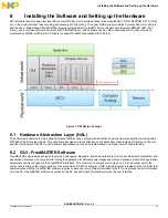
Installing the Software and Setting up the Hardware
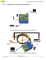
In order to perform the demonstration examples, first setup the evaluation board hardware and software as follows:
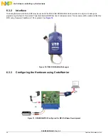
1. Connect the P&E USB Multilink Debugger between the reference design board and the computer.
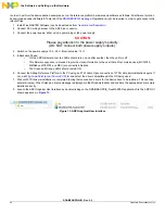
2. Wait until P&E USB Multilink Debugger drivers installation is completed (during first connection, drivers for the device have to be
installed. This can take several minutes). When finished, a status message is displayed in the Windows taskbar and confirms the
appropriate drivers were installed correctly.
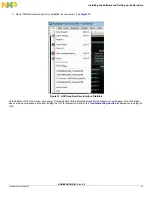
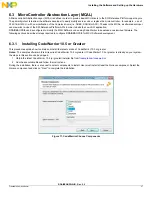
3. Launch the CodeWarrior Suite.
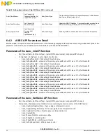
4. Connect the power supply, either using a power plug or lab power supply.
CAUTION
Please pay attention to the power supply's polarity.
(DO NOT connect both power supply’s inputs).
5. Switch on the power supply at 5.2 to 20 V.
6. Connect ECU wiring harness to the ARP blue connector.
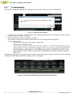
7. Start development of your application using CodeWarrior.
6.4 Complex Drivers
6.4.1
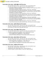
Airbag System Basis Chip (ASBC) SW Driver
Table 22: Airbag System Basis Chip SW Driver API
Function Name
Function Parameters
Return Type
Function Description
Asbc_Init
Spi_Channel [in]
*Config [in]
Asbc_ReturnType
Initialize the Airbag System Basis Chip and returns the
confirmation of initialization. Multiple initialization configuration is
supported via the Config parameter.
Asbc_GetStatus
Spi_Channel [in]
*Status [out]
Asbc_ReturnType
Return the status of the ASBC. Only the general statuses are
reported via this service.
Asbc_SetAnlMuxSource
Spi_Channel [in]
Source [in]
Asbc_ReturnType
Allow to change the analog parameter which is connected to the
AOUT output.
Asbc_SetDcsMuxSource
Spi_Channel [in]
Source [in]
Voltage [in]
Asbc_ReturnType
Determines which DC sensor input channel shell be connected for
diagnostic output.
Asbc_SetVregMode
Spi_Channel [in]
*Config [in]
Asbc_ReturnType
Set the ASBC Voltage regulator. Various configurations of voltage
regulators are supported via the Asbc_VregConfig container.
Asbc_GetVregStatus
Spi_Channel [in]
*Status [out]
Asbc_ReturnType
Return the status of the ASBC Voltage regulators. This also
contains the Boost and Buck statuses.
Asbc_SetPsi5Mode
Spi_Channel [in]
*Config [in]
Asbc_ReturnType
Set the ASBC PSI5 four satellite sensor interface. Various
configurations of PSI5 interface are supported via the
Asbc_Psi5Config container.
Asbc_GetPsi5Status
Spi_Channel [in]
*Status [out]
Asbc_ReturnType
Return the status of the ASBC PSI5 interface.
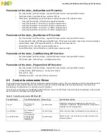
Asbc_SetLinMode
Spi_Channel [in]
*Config [in]
Asbc_ReturnType
Set the ASBC LIN transceiver mode. Via the Asbc_LinConfig
configuration container various configurations are supported.
Asbc_GetLinStatus
Spi_Channel [in]
*Status [out]
Asbc_ReturnType
Return the ASBC LIN transceiver status.
Asbc_SetGpo
Spi_Channel [in]
GpoChannel [in]
GpoPwmDutyCycle [in]
GpoDriverConfig [in]
Asbc_ReturnType
Set the ASBC output channel mode. Various configuration for each
output channel are supported via the Asbc_GpoDriverConfig
configuration container.
Asbc_GetGpoStatus
Spi_Channel [in]
GpoChannel [in]
*Status [out]
Asbc_ReturnType
Return the ASBC output channel status. This includes the
high/low-side selection, thermal shutdown and the voltage level.