


RDAIRPABPSI5UG , Rev. 2.0
18
Freescale Semiconductor, Inc.
Describing the Device Functions
5.2.4
Configuration - Arming Threshold
For each axis, both the positive and negative threshold can be set above which and when the arming window requirements are met, the
arm outputs will be set to active as defined in the arming operations register.
In the startup phase, the threshold can be set to such a level that when the self test deflection is triggered, the arming outputs will become
active. This can be used as part of the self-test at startup. After completion of the self test, thresholds should be set back to the correct
application values, and before the configuration is complete, by setting the 'ENDINIT' bit, after which no further configuration changes can
be made.
The complete startup and self-test procedure is described in the ARP specification (Airbag Reference Platform).
Note that after the configuration is complete and the 'ENDINIT' bit is set, a CRC check of the configuration is carried out in the background,
which will lead to an error in the status register if a configuration bit flips.
5.2.5
Status
Internal errors are flagged in the DEVSTAT register.
5.3 MC33797 - Four Channel Squib Driver (FCS)
The ARP uses two Four Channel Squib Drivers (FCS) configured in cross-coupled mode to safely implement eight squib drivers.
The four channel squib driver is addressed using an 8-bit SPI interface over which commands and data are sent.
The only configuration possible is the time the device remains enabled after the fire enable (FEN1, FEN2) pins have been activated. This
is equivalent to the arming pulse stretch time applied to the safing output on both the system basis chip and the local ECU sensor. Two
commands are required to change this time - first is an unlock command and second is the programmed time between 0 and 255 ms.
Default is 0 ms.
Firing the squibs also requires two commands - the first arms one of the banks of drivers, the second turns on the required switches. More
than one switch can be turned on by a single command.
The majority of the commands relate to diagnostics of the four channel squib driver and the connected squibs. A full list of diagnostic
commands is available in the ARP specification (Airbag Reference Platform).
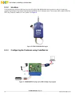
5.4 MMA5xxx High G Satellite Collision PSI5 Sensor
Configuration of the device is done off line prior to assembly in the system.
As soon as the device is switched on, it will begin an internal configuration and self test, and also sends initialization data, which is received
in the system basis chip and checked by the application. Once the device has completed sending the initialization data, which concludes
with an OK or NOK message, it enters normal operation and starts sending sensor data, either autonomously if in asynchronous mode,
or in response to SYNC pulses on the satellite sensor interface if in synchronous mode.
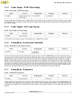
Table 20. Configuration - Arming Threshold
Define
Function
Config Register
Diagnosis
Comment
MMA6813KW
Configuration
ARMT_XP, ARMT_XN
ARMT_YP, ARMT_YN
–
Table 21. Status
Define
Function
Config Register
Diagnosis
Comment
MMA6813KW
Status
–
DEVSTAT