


RDAIRPABPSI5UG , Rev. 2.0
Freescale Semiconductor
15
Describing the Device Functions
5.1.4
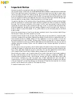
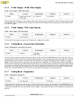
Power Supply - SYNC Pulse Supply
Default setting for the SYNC supply is OFF. Firmware needs to turn the SYNC supply on through PS_CONTROL register only if the satellite
sensors are operating in synchronous mode. Firmware can monitor VSYNC voltage through the analog output pin selected through the
AI_CONTROL register.
5.1.5
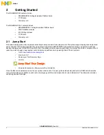
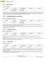
Power Supply - ECU Logic Supply
The internal ECU logic supply is always on and firmware has no configuration to perform.
5.1.6
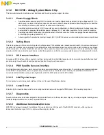
Safing Block - Sensor Data Thresholds
In order to be able to change the sensor data threshold value or values at which the ARM/DISARM pins are set to their active states (i.e.
the system is armed when a sensor value exceeds the defined threshold), a secure firmware sequence must be carried out to unlock the
threshold register using T_UNLOCK. Once that is done, the threshold can be changed by firmware through the SAFE_TH_n register.
Notes:
There is no special firmware required to input sensor data into the safing block. The SPI protocol on the sensor SPI interface is
the same to both the local sensor and the satellite sensor interfaces on the system basis chip, and whenever the microcontroller reads a
sensor value, the response from the sensor or system basis chip is recognized as being sensor data, and is automatically read into the
safing block. The only requirement the application has to meet is that the sensor data is read in the correct sequence, starting with the
local sensor X-axis data followed by the Y-axis, and then the satellite sensor interfaces on the system basis chip.
5.1.7
Safing Block - Diagnostics
The firmware has the capability to change the mode in which the safing block is operating, so that diagnosis of the ARM/DISARM pins can
be diagnosed or the scrapping mode (i.e. the system is armed when no sensor data exceeds any threshold, used to fire all squibs when
a vehicle is being scrapped) can be entered. Either of these changes is only possible at startup prior to the safing block entering normal
operation.
Table 8. Power Supply – SYNC Pulse Supply
Define
Function
Config Register
Diagnosis
Comment
MC33789
Satellite Sensor SYNC
Pulse Supply
PS_CONTROL
AI_CONTROL
Table 9. Power Supply - ECU Logic Supply
Define
Function
Config Register
Diagnosis
Comment
MC33789
Linear Regulator
–
–
Table 10. Safing Block - Sensor Data Thresholds
Define
Function
Config Register
Diagnosis
Comment
MC33789
Threshold
T_UNLOCK,
SAFE_TH_n
–
Table 11. Safing Block - Diagnostics
Define
Function
Config Register
Diagnosis
Comment
MC33789
Linear Regulator
–
SAFE_CTL