NXP Semiconductors MMPF0100 Скачать руководство пользователя страница 22

AN4536 Application Note Rev. 2.0 1/2014

22

Freescale Semiconductor

OTP Overview

2.5.2

Error Correction Code (ECC)

Error correction is off by default, but it is recommended for all OTP programming operations. When enabled, it 
reports and corrects a single bit error per fuse bank, but only reports a double bit error per fuse bank. Fuses may be 
programmed without using ECC. However, after verifying that the part is configured properly, ECC may enabled, 
and the error check bits can be programmed. 

It should be noted that double bit errors can prevent regulators from powering up, or can result in a configuration 
that does not match the external components. Although such occurrence is rare, it is still a good practice to employ 
ECC to at least alert the user of such an occurrence.

Note: The desired function of the redundant bits must be determined when ECC is configured and its bits 
programmed, or the ECC logic attempts to correct the newly programmed redundant bits. 

Sections 

2.5.2.1

 through 

2.5.2.3

 are for advanced users. For a simple script that enables ECC, proceed to section 

OTP Programming Example

.

2.5.2.1

ECC Interrupt

With ECC enabled, if a single fuse in a bank has the wrong value, the ECC logic corrects that bit and the corrected 
value is loaded into the TBBOTP register for that bank. The single error bit for that bank is set and also the main 
interrupt ECC bit is set. If two or more bits are in error, in a bank, the ECC is not able to correct them. The double 
error bit error for that bank is set and the ECC interrupt bit is set. The single error and double error bits may be read 
from registers 0x8A to 0x8D in the Extended Page1 of the register map. The ECC interrupt bit may be read from 
register, 0xE, on the functional page of the register map.

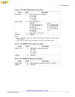
Table 34. ECC Error Detection Registers 

Extended Page 1

I

2

C Data Bits

Addr

Reg Name

7

6

5

4

3

2

1

0

8A

OTP ECC SE1

ECC5_SE ECC4_SE ECC3_SE ECC2_SE ECC1_SE

x

x

x

0

0

0

0

0

8B

OTP ECC SE2

ECC10_SE ECC9_SE ECC8_SE ECC7_SE ECC6_SE

x

x

x

0

0

0

0

0

8C

OTP ECC DE1

ECC5_DE ECC4_DE ECC3_DE ECC2_DE ECC1_DE

x

x

x

0

0

0

0

0

8D

OTP ECC DE2

ECC10_DE ECC9_DE ECC8_DE ECC7_DE ECC6_DE

x

x

x

0

0

0

0

0

Содержание MMPF0100

Страница 1: ...e SMARTMOS process a combinational BiCMOS manufacturing flow that integrates precision analog power functions and dense CMOS logic together on a single cost effective die MMPF0100 OTP Programming Inst...

Страница 2: ...ritten to and used for startup of the MMPF0100 Contents of the TBBOTP registers can be maintained in the absence of the main input supply VIN by using a coin cell at the LICELL pin 2 1 Power up Config...

Страница 3: ...100 by changing the state of these fuses as required during the OTP programming process There are 10 banks of fuses with each bank consisting of 26 fuses Of the 26 fuses in a bank 20 are programmable...

Страница 4: ...5 V WRITE_I2C D1 0B Vgen3 Sequence 11 WRITE_I2C D4 00 Vgen4 Voltage 1 8 V WRITE_I2C D5 07 Vgen4 Sequence 7 WRITE_I2C D8 0A Vgen5 Voltage 2 8 V WRITE_I2C D9 0C Vgen5 Sequence 12 WRITE_I2C DC 0F Vgen6...

Страница 5: ...s VPGM ON Turn ON 9 5 V supply for PF0100A Turn ON 9 0 V supply for PF0100 VPGM ON turns on supply to the VDDOTP pin DELAY 500 Adds 500 msec delay to allow VPGM time to ramp up PF0100 OTP MANUAL PROGR...

Страница 6: ...ANK 6 WRITE_I2C F6 03 Set Bank 6 ANTIFUSE_RW and ANTIFUSE_BYPASS bits WRITE_I2C F6 0B Set Bank 6 ANTIFUSE_EN DELAY 100 Allow 100ms for PF0100A Use 50 ms for PF0100 WRITE_I2C F6 03 Reset Bank 6 ANTIFUS...

Страница 7: ...ms for PF0100 WRITE_I2C FA 03 Reset Bank 10 ANTIFUSE_EN WRITE_I2C FA 00 Reset Bank 10 ANTIFUSE_RW and ANTIFUSE_BYPASS bits WRITE_I2C D0 00 Clear WRITE_I2C D1 00 Clear VPGM OFF Turn off 8 5 V Boost Sup...

Страница 8: ...e WRITE_I2C A8 2B Sw1c Voltage 1 375 V WRITE_I2C A9 02 Sw1c Sequence 2 WRITE_I2C AA 01 Sw1c Freq 2 0 MHZ WRITE_I2C AC 72 Sw2 Voltage 3 30 V WRITE_I2C AD 05 Sw2 Sequence 5 WRITE_I2C AE 01 Sw2 Freq 2 MH...

Страница 9: ...mV us SeqCLK 2 ms PWRON config 0 WRITE_I2C E1 0E Power up DVS 1 5625 mV us SeqCLK 2 ms PWRON config 0 WRITE_I2C E2 0E Power up DVS 1 5625 mV us SeqCLK 2 ms PWRON config 0 WRITE_I2C E8 00 Power Good D...

Страница 10: ...LSBs of the slave address 19 OTP EN ECC0 EN_ECC_BANK1 Enable ECC for OTP fuse bank 1 25 20 ECC check bits for fuse bank 1 Table 3 Bank 2 Fuses Register Name Register bits Description 5 0 OTP SW1C VOL...

Страница 11: ...FDDR power up sequence 19 OTP EN ECC0 EN_ECC_BANK5 Enable ECC for OTP fuse bank 5 25 20 ECC check bits for fuse bank 5 Table 7 Bank 6 Fuses Register Name Register bits Description 6 0 OTP SW 4 VOLT SW...

Страница 12: ...nce 18 RSVD 19 OTP EN ECC1 EN_ECC_BANK 8 Enable ECC for OTP fuse bank 8 25 20 ECC check bits for fuse bank 8 Table 10 Bank 9 Fuses Register Name Register bits Description 3 0 OTP VGEN5 VOLT VGEN5_VOLT...

Страница 13: ...POR1 FUSE_POR1 Loads fuse values to TBBOTP registers bit is XORed 7 6 OTP PU CONFIG2 SEQ_CLK_SPEED2 1 0 Power up sequence delay bits are XORed 9 8 OTP PU CONFIG2 SWDVS_CLK2 1 0 Power up slew rate for...

Страница 14: ...operation mode and frequency selection OTP SW3B VOLT 0xB4 SW3B OTP Output voltage set point OTP SW3B SEQ 0xB5 SW3B OTP power up sequence selection OTP SW3B CONFIG 0xB6 SW3B OTP frequency selection OT...

Страница 15: ...Single Phase 10 A B Dual Phase 11 A B Independent mode VTT 4 Enable SW4 in VTT mode 4 UNUSED 7 5 UNUSED Notes 3 Only on OTP SW1AB CONFIG and OTP SW3A CONFIG registers UNUSED on all other OTP SWx CONFI...

Страница 16: ...int OTP VGEN4 SEQ 0xD5 VGEN4 OTP power up sequence selection OTP VGEN5 VOLT 0xD8 VGEN5 OTP output voltage set point OTP VGEN5 SEQ 0xD9 VGEN5 OTP power up sequence selection OTP VGEN6 VOLT 0xDC VGEN6 O...

Страница 17: ...mentioned The XORed bits are read only Table 23 OTP Redundant Bits Registers Extended Pg 1 I2 C Data Bits Addr Reg Name 7 6 5 4 3 2 1 0 E0 OTP PU CONFIG1 PWRON CFG1 SWDVS_CLK1 1 0 SEQ_CLK SPEED1 1 0...

Страница 18: ...2 SWDVS_CLK_XOR Final result of the XOR function of the SWDVS_CLKx 1 0 bits 4 PWRON_CFG_XOR Final result of the XOR function of the SEQ_PWRON_CFGx bits 7 5 RSVD Reserved Table 26 OTP_FUSE_PORx Bits De...

Страница 19: ...or Correction Code ECC 2 4 3 OTP Register Reloading without Turn on Event After the fuses are programmed their values may be loaded into the digital control logic without toggling VIN or PWRON To upda...

Страница 20: ...the OTP fuse latch from the analog fuse bit 0 Disable loading 1 Enable loading 2 RL_OTP_ECC Reload the OTP ECC registers Set this bit irrespective of whether ECC is enabled or disabled 0 Disable loadi...

Страница 21: ...nd Table 33 for a description of the registers Table 31 OTP Fuse Read Enable Register FSL Extended Page 1 I2 C Data Bits Addr Register Name 7 6 5 4 3 2 1 0 80 OTP FUSE READ EN OTP_FUSE_READ_EN 0 0 0 0...

Страница 22: ...2 5 2 1 through 2 5 2 3 are for advanced users For a simple script that enables ECC proceed to section OTP Programming Example 2 5 2 1 ECC Interrupt With ECC enabled if a single fuse in a bank has the...

Страница 23: ...nk 4 0 No single error detected 1 Single error detected 4 ECC5_SE 0 Single error detection in fuse bank 5 0 No single error detected 1 Single error detected 7 5 RSVD 0 Reserved OTP ECC SE2 0 ECC6_SE 0...

Страница 24: ...2 ECC3_DE 0 Dual error detection in fuse bank 3 0 No single error detected 1 Single error detected 3 ECC4_DE 0 Dual error detection in fuse bank 4 0 No single error detected 1 Single error detected 4...

Страница 25: ...ead from bits 5 0 in registers 0xE1 to 0xEA in the Extended Page 2 See Table 37 For example if there is an error in bit 5 of fuse bank 3 reading bits 5 0 of register 0xE3 yields a hexadecimal code of...

Страница 26: ...section To determine if there was an error when programming fuses the following options are available Checking the fuse values against what was written Monitor the INTB signal but first the ECC inter...

Страница 27: ..._CIN ECC6_CIN_TBB 5 0 0 0 0 0 0 0 0 0 E7 ECC_CTRL7 ECC7_EN_TBB ECC7_CALC_CIN ECC7_CIN_TBB 5 0 0 0 0 0 0 0 0 0 E8 ECC_CTRL8 ECC8_EN_TBB ECC8_CALC_CIN ECC8_CIN_TBB 5 0 0 0 0 0 0 0 0 0 E9 ECC_CTRL9 ECC9_...

Страница 28: ...ons have to be made Figure 1 Minimum OTP Programming Requirements Diagram VPGM SDA SCL 56 55 54 53 52 51 50 49 48 47 46 45 44 43 1 2 3 4 5 6 7 8 9 10 11 12 13 14 15 16 17 18 19 20 21 22 23 24 25 26 27...

Страница 29: ...to the processor especially when the processor is unpowered due to a yet to be programmed MMPF0100 It is recommended to isolate the SCL SDA lines going to the processor while communicating with the M...

Страница 30: ...ly to power the VIN and VDDIO rails of the MMPF0100 Figure 4 shows how to interface the KITPFPGMEVME with the MMPF0100 in an application board For applications which use a single rail for VIN and VDDI...

Страница 31: ...ng an analog switch as shown in Figure 5 When the signal Programmer_Select_O P is low the system VDDIO supply is connected to the VDDIO pin When Programmer_Select_O P is high VIN and VDDIO are connect...

Страница 32: ...ce OTP programming is completed The Programmer_Select_O P signal can be generated using the GPIO2 pin on the KITPFPGMEVME Controlling this signal can be part of the programming script 3 3V Regulator f...

Страница 33: ...shown in Figure 6 Note Using the analog switch may not be the most cost effective option to isolate the I2C bus Similar functionality can be achieved by using solder shorts or 0 Ohm resistors However...

Страница 34: ...les analog doc data_sheet MMPF0100 pdf MMPF0100ER Errata http cache freescale com files analog doc errata MMPF0100ER pdf PFSERIESFS Fact Sheet http cache freescale com files analog doc fact_sheet PFSe...

Страница 35: ...5 Revision History 5 Revision History Revision Date Description 2 0 5 2013 Initial release 3 0 1 2014 Updated section 2 2 OTP Programming Example Added Section 2 3 Try Before Buy Mode Example page 8 D...

Страница 36: ...pecifically disclaims any and all liability including without limitation consequential or incidental damages Typical parameters that may be provided in Freescale data sheets and or specifications can...

Отзывы: