- 38 -
JUMBO NT
setzungen an tragenden Teilen
(z. B. Schweiß-
arbeiten) ist eine Überprüfung
durch einen Sachverständigen
erforderlich. (außerordent-
liche Sicherheitsüberprüfung)
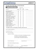
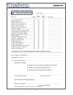
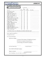
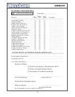
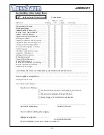
Dieses Prüfbuch enthält Formulare mit
aufgedrucktem Prüfplan für die
Sicherheitsüberprüfung. Verwenden
Sie bitte das entsprechende Formular,
protokollieren Sie den Zustand der
geprüften Hebebühne und belassen Sie
das vollständig ausgefüllte Formular
in diesem Prüfbuch.
9. Montage und Inbetriebnahme
9.1 Aufstellung der Hebebühne
Der Aufstellungsort des
Bedienaggregat kann in zwei
Varianten gewählt
werden. Entweder
in Auffahrrichtung vorne rechts oder
in Auffahrrichtung vorne links.
9.2 Aufstellungsrichtlinien
• Die Aufstellung der Hebebühne
erfolgt durch geschulte Monteure
des Herstellers oder der
Vertragshändler. Falls der
Betreiber über entsprechend
geschulte Monteure verfügt, kann
die Hebebühne auch von ihm
aufgestellt werden. Die Aufstellung
ist gemäß der Montageanleitung
durchzuführen.
• Die serienmäßige Hebebühne darf
nicht in explosionsgefährdeten
Räumen oder Waschhallen
aufgestellt werden.
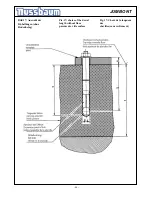
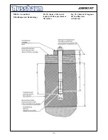
• Vor der Aufstellung ist ein
ausreichendes Fundament
nachzuweisen oder gemäß den
Richtlinien des
Fundamentplanes
zu erstellen (siehe Fun-
damentplan). Der Aufstellplatz
muß plan eben sein. Fundamente
im Freien und in Räumen, in denen
mit Winterwitterung oder Frost zu
rechnen ist, sind frosttief zu
gründen.
des fiches contenant le plan à suivre
pour le contrôle de sécurité.
9. Montage et mise en service
9.1 Mise en place du pont
élévateur
En modèle standard, l’emplacement
prévu pour la pupitre de commande
se trouve dans le sens d’engagement
à gauche ou bien à droite.
9.2 Directives de mise en place
• L’installation du pont élévateur
doit être effectué par des monteurs
du fabricant ou des
concessionnaires formés. Si
l’utilisateur dispose lui-même de
monteurs formés il peut procéder
lui même à l’installation.
L’installation doit être effectuée
selon les instructions fournis.
• Le pont élévateur de série ne doit
pas être installée dans des locaux à
atmosphère explosive ou dans des
halles de lavage.
• Avant la mise en place du pont
élévateur, il faut justifier de
fondations suffisantes ou réaliser
celles-ci
conformément au
directives du plan de fondation
(voir plan). L’emplacement doit
être bien plan. En cas d’installation
à l’extérieur ou dans des halles
soumises au gel et à des conditions
hivernales le fondement doit être
mis hors gel.
• Le raccordement électrique à
prévoir est de 3 ~/N + PE, 400V,
50Hz. La ligne électrique doit être
protégée par des fusibles. Le point
de raccordement se trouve dans la
pupitre de commande.
• Pour protéger les câbles
Please us the adequate form for the
security checks. The form should
remain in this manual after they have
been filled out. In the following there
is a short description about special
safety devices.
9. Installation and Initiation
9.1 Installation of the automotive lift
You can choose between two
installation places of the operating unit:
The position of the operating unit is in
drive-in direction right or in drive-in
direction left.
9.2 Regulations for the installation
• The installation of the lift is
performed by trained technicians of
the manufacturer or its distribution
partner. If the operator can provide
trained mechanics, he can install
the lift by himself. The installation
has to be done according to this
regulation.
• The standard lift must not be
installed in hazardous locations or
washing areas.
• Before installation a sufficient
foundation must be proved or
constructed.
• An even installation place has to be
provided. The foundations must be
based in a frost resistance depth,
both outside and indoors,
where
you must reckon with frost.
• An electrical supply 3~/N+PE, 400
V, 50 Hz has to be provided. The
supply line must be protected with
16 Ampere time lag (VDE0100
German regulation). The minimum
diameter amounts to 2,5 mm².
• All cable ducts have to be equipped
with protective coverings to prevent
accidents.
9.3 Erection and doweling of the lift
• Install the lift according to the data
sheet and the foundation plan
• Install the operating unit at its
designed place.
• Fill in hydraulic oil,
approx. 14
Содержание Jumbo NT
Страница 14: ...14 JUMBO NT 2 5 Konformit tserkl rung 2 5 attestation of conformity 2 5 D claration de conformit...
Страница 16: ...16 JUMBO NT 3 3 Datasheet 3 3 Fiche technique 3 3 Datenblatt...
Страница 18: ...18 JUMBO NT...
Страница 19: ...19 JUMBO NT...


