4
E
.0
4.
20
00
•
G
. 1
6.
11
.1
0
Technical specifications
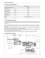
6. Technical specifications
7. Functional description
The fuel is pumped out of the supply tank and into the burner tank. A float switch controls the level inside
the burner tank. An additional microswitch serves as a limiter, switching over to fault mode when the tank
is overfilled.
A thermostat regulates the oil temperature in the burner tank and starts the burner when the set tempera-
ture is reached. Thereafter, the automatic oil burner control system controls and monitors the operation of
the burner.
Fuel is aspirated and finely atomised by a special nozzle using the compressed air flowing through the
burner, which is used as primary air for the combustion process.
The burner blower supplies the secondary air which is added to the atomised spray at the baffle plate. This
ensures full combustion and operational reliability.
At the oil temperature in excess of 150° C, the safety switch automatically de-energises the burner.
8. Air/oil flow schematic
Burner type
Technical specifications
G100
Output, fuel oil
KW
70 - 132
Output, rapeseed oil
KW
65 - 101
Oil throughput
kg/h
8.6
Compressor output
m
3
/h
11.5
Primary air connection
bar
0.4 - 1.5
Motor output
W
180
Heating element
W
1100
Voltage
1/N/PE ~50 Hz 220 - 240 V
Weight
kg
21
Feed line
Contact switch
Heating cartridge
E1 + E2
Overflow tank
Burner tank
Thermostat
F1
Safety valve
Pressure gauge
Solenoid valve
Y1
Primary air actuator
Pressure controller
Connecting line
baffle plate
Burner pipe
Nozzle
Nozzle assembly
Oil line
Fan wheel
M1
Micro-switch,
overflow protection
S1
Micro-switch,
level control
S2
Содержание G100 Universal
Страница 1: ...G100 Universal Oil Burner Installation Maintenance Manual...
Страница 15: ......

