11
E
. 0
4.
20
00
•
G
. 1
6.
11
.1
0
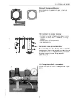
Circuit diagram
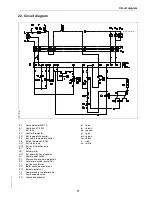
22. Circuit diagram
S
P
_
1
-5
7
9
Boiler controller
B1
Flame detector MZ770
E1
Heating coil 1100 W
F
Ext. fuse
F1
Control thermostat
F21
Ext. temperature control
F3
Ext. safety temperature limiter
F6
Safety thermostat (STB)
H11
Ext. status lamp
H13
Ext. fault indication lamp
K1
Relay
M1
Burner motor
P11
Ext. operating hours counter
Q1
Heater power switch
S1
Micro-switch, overflow protection
S2
Level micro-switch (pump SV)
T1
Ignition transformer
X11
Boiler control connector unit
X12
Burner socket unit
Y1
Compressed air solenoid valve
Y2
Pump solenoid valve
PE
Grounded conductor
bl
= blue
br
= brown
ge = yellow
gr
= grey
grü = green
sw = black
rt
= red
ws = white
Содержание G100 Universal
Страница 1: ...G100 Universal Oil Burner Installation Maintenance Manual...
Страница 15: ......

