NOVUS AUTOMATION
12/57
●
Internal Diagnostic Sensors:
○
The Internal Diagnostic Sensors inform the voltage of the possible
LogBox-BLE
power supplies;
○
The maximum resolution for the Internal Diagnostic Sensors is 0.01 V;
○
You can configure them to be displayed with 0, 1, or 2 decimal places;
○
The unit of measure for these sensors is Volts and no unit symbol is displayed.
The accuracy of these types of signals is described in the chapter TECHNICAL SPECIFICATIONS. The connection of these signals is described in
chapter INSTALLATION.
An analog/digital (A/D) converter with high resolution and accuracy is used to read the sensors connected to the analog channel inputs. In the
desired scan range, all the analog channels enabled will be read.
Each type of input signal has a valid measuring range (detailed in chapter TECHNICAL SPECIFICATIONS). However, the device typically can
measure signals which slightly exceed the limits of this range. How much it can measure beyond the range depends on the type of input configured
and might vary between different device.
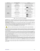
The following table describes what to expect in the
LogBox-BLE
display according to the signal applied to the input for each configured input type.
6.1.1
MEASUREMENT AND INDICATION OF INPUT TYPES
INPUT TYPE
INPUT SIGNAL CONDITION
INDICATION
Pt100
Within range
Read input value
Pt100 with one or more wires disconnected
----
will be displayed
Slightly above the upper limit
-22000 will be logged in the memory
Slightly under the lower limit
Read input value
*
Far above the upper limit
vvvv
will be displayed
32767 will be logged in the memory
Far under the lower limit
nnnn
will be displayed
-32000 will be logged in the memory
Thermocouples
J, K, T, E, N, R, S, and B
Within range
Read input value
Open Thermocouple
----
will be displayed
-22000 will be logged in the memory
Slightly above the upper limit
Read input value
*
Slightly under the lower limit
Read input value
*
Far above the upper limit
vvvv
will be displayed
32767 will be logged in the memory
Far under the upper limit
nnnn
will be displayed
-32000 will be logged in the memory
Voltage
0 to 50 mV
Within range
Read input value converted into User Range
Disconnected signal
----
will be displayed
-22000 will be logged in the memory
Slightly above the upper limit
Read input value converted into User Range
*
Slightly under the lower limit
Read input value converted into User Range
*
Far above the upper limit
vvvv
will be displayed
32767 will be logged in the memory
Far under the lower limit
nnnn
will be displayed
-32000 will be logged in the memory
Voltage
0 to 5 V
0 to 10 V
Within range
Read input value
Disconnected signal
0 V value converted into User Range
Slightly above the upper limit
Read input value converted into User Range
*
Slightly under the lower limit
Read input value converted into User Range
*
Far above the upper limit
vvvv
will be displayed
32767 will be logged in the memory
Far under the lower limit
nnnn
will be displayed
-32000 will be logged in the memory


