


Chapter 4 SMART7 with SPAN Operation
SMART7 Installation and Operation User Manual v6
63
The order of rotations is Z-X-Y and all rotations are right handed.
Generally, frames of reference are defined as Z up, with Y forward, and X completing the right-handed system.
An example is the Vehicle frame, where Z is always considered to be upwards, Y forward through the direction of
travel, and X to the right.
If the SMART7 is installed with the front of the SMART7 facing the direction of forward motion for the vehicle (as
shown in
on page 27), an IMU Body frame to Vehicle frame rotation is not
required. The necessary rotations are configured at the factory.
An IMU Body frame to Vehicle frame calibration routine should be run to on all SMART7 installations,
whether an IMU Body frame to Vehicle frame rotation is required or not. See
on page 76 or
Multi-Line Body to Vehicle Frame Rotation Calibration
on page 77 for more information. This calibration routine should be done each time the
SMART7 is remounted.
Non-Standard Installation
The SMART7 is intended to be installed with the front of the SMART7 facing the direction of vehicle travel. If the
installation location does not allow this orientation, the
SETINSROTATION RBV
command must be used to
align the SMART7 IMU Body frame with the Vehicle frame.
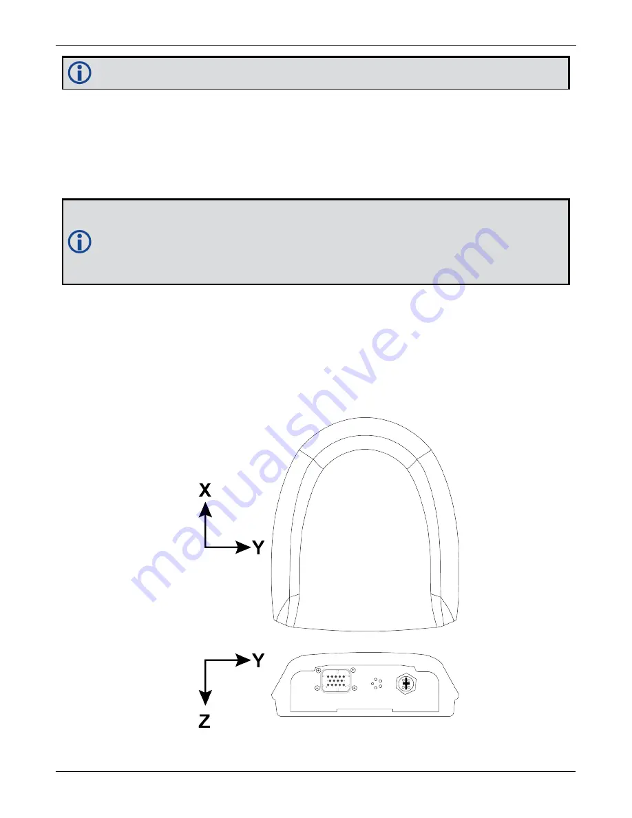
The IMU Body frame of the SMART7-S is shown in
Figure 20: SMART7-S and SMART7-SI IMU Body Frame
Figure 20: SMART7-S and SMART7-SI IMU Body Frame


