background image

Copyright © 2020, ASSA ABLOY Accessories and Door Controls Group, Inc. All rights reserved. Reproduction in whole or

in part without the express written permission of ASSA ABLOY Accessories and Door Controls Group, Inc. is prohibited.

80-9360-1037-020  Rev 3  11/20

20

D6001DE-L Double Unit Series (Double Egress)

 Power Operator

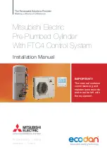
Double Door Fail Safe Electric Strike or Electromagnetic Lock 24VDC Wiring

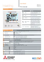
Double Door 24VDC Electric Exit Device Wiring

Factory Pre-Wiring in Illustration is for this functionality

Change Factory Pre-Wiring to Illustration Below (move NO to NC)

•  For Master/Follow or 

Master-Coord/Follow only 

(Sync Cable must be used 

to connect inverters .)

•  Doors are normally closed 

and latched . 

•  Activating switch will 

energize exit device and 

door will automatically 

open . Exit device will 

stay energized based on 

Latch Rtrct setting . Door 

will close after hold open 

time delay has expired . 

•  Current draw at Power 

Outputs not to exceed 

1 .3 amps .

•  For Master/Follow or 

Master-Coord/Follow only 

(Sync Cable must be used 

to connect inverters .)

•  Doors are normally closed 

and latched . 

•  Activating switch will 

unlock electric strike or 

mag lock and door will 

automatically open . Door 

will close after hold open 

time delay has expired . 

•  Door will remain 

unlocked during power 

failure . 

•  Current draw at Power 

Outputs not to exceed  

1 .3 amps .

Содержание Assa Abloy D6001DE-L Series

Страница 1: ...0SUP Power Module Sub assembly 6001PM Closer Assembly 7500LAP Pour la version francaise voir www nortondoorcontrols com READ AND FOLLOW ALL INSTRUCTIONS SAVE THESE INSTRUCTIONS This product can expose...

Страница 2: ...rs can be installed and adjusted to conform with A D A regulations ANSI A117 1 These door controls permit door assemblies to conform to the requirements of this specification for buildings and facilit...

Страница 3: ...hers required Closing When the hold open time has elapsed the door closer will close the door automatically The door will slow to low speed at latch before it reaches the fully closed position The doo...

Страница 4: ...emplate information based upon use of 5 maximum width butt hinges Frame reveal is 2 1 4 to 4 3 4 for push arm and 1 8 to 3 for pull arm Before beginning the installation verify that the door frame is...

Страница 5: ...ckplates can be used as reference NOTE If frame is not flat or is twisted additional steel back plates or shimming is required Failure to mount units properly can result in improper function of operat...

Страница 6: ...igure 5 6 Using backplate as template mark conduit slot and Dim D mounting hole Figure 5 NOTE Dim D should be 1 up from frame rabbet if backplate is properly aligned 7 Drill hole for mounting screw at...

Страница 7: ...between backplate and wall above header is HIGHLY recommended Material must comply with local codes Failure to properly secure top of backplate could result in operator being allowed to rock during op...

Страница 8: ...ge edge of frame Slide each LAP over two 2 screws and tighten Figure 11 NOTE LAP for left door should have PUSH label and door closer valves should point toward chain LAP for right door should have PU...

Страница 9: ...mbly so two 2 conduit holes are at bottom and text on wire input label is legible Figure 13 2 Secure assembly to backplate using four 4 8 32 x 5 16 Phillips head screws Figure 13 WARNING BUILDING POWE...

Страница 10: ...ne way Install Operator Figure 16 Access Door Union Assembly View From Floor Spacer Spacer Union Assembly Mounting Screw typical Figure 17 Power Module Sub assembly 4 Pin Black Connector Power Module...

Страница 11: ...ugh shoe and into sex bolts Figure 19 NOTE Orient shoe with long side of shoe toward hinge Figure 20 View from ceiling looking downward 1 Open left door 2 Slide forearm into main arm adjusting tube Fi...

Страница 12: ...as shown Figure 28 4 Secure arm to pinion with 1 4 20 x 1 2 screw and countersunk patch washer Figure 27 5 Insert stud on arm into slider in track by pressing clip on backside of slider onto stud Fig...

Страница 13: ...door open When finished slide access door closed and reinsert 6 Torx flat head screw to secure door Figure 32 Adjustments A Adjust mechanical closer features on each operator NOTE Make necessary mech...

Страница 14: ...ight to increase decrease value NOTE Values will auto save 3 seconds after adjustments Figure 33 Figure 34 View From Floor Union Assembly Selector Mode Switches WARNING Door may begin to move immediat...

Страница 15: ...e set Master door will open slightly before Follower door during opening cycle Upon closing if Master door reaches a set door opening position MasterStopOffset and Figure 35 Union Assembly Switches Fo...

Страница 16: ...ackplate verify backplate is not warped or twisted Additional support or shimming may be required See Sections A B under Prepare Frame and Door WARNING Make sure no wiring is loose or can be caught by...

Страница 17: ...ice connected to Aux 1 is sending constant signal Aux 2 Stuck Activation device connected to Aux 2 is sending constant signal Aux 3 Stuck Activation device connected to Aux 3 is sending constant signa...

Страница 18: ...doors when door coordination is needed MastStopOffset 0 500 180 Adjustable point where Master Coord door will stop and wait for Follower door to fully close so Follower does not contact astragal attac...

Страница 19: ...d Function with Switches For Master Follow or Master Coord Follow only Sync Cable must be used to connect inverters Doors are normally closed Fail Secure Electric Strike 24VDC Wiring For Master Follow...

Страница 20: ...o NC For Master Follow or Master Coord Follow only Sync Cable must be used to connect inverters Doors are normally closed and latched Activating switch will energize exit device and door will automati...

Страница 21: ...losed Activating switch will open door Door will remain in indefinite hold open until activating switch is activated a second time causing door to close Change Factory Pre Wiring to Illustration Below...

Страница 22: ...be used to connect inverters Doors are normally closed and latched Fire Alarm activation will retract exit device latch bolt and door operator will open door Door will remain open until the Fire Alarm...

Страница 23: ...hed Activating wireless switch or hand held wireless transmitter will open door Door will remain in indefinite hold open until wireless switch or hand held transmitter is activated a second time causi...

Страница 24: ...e normally closed and latched Activating outside door switch will open outside door After vestibule time delay has elapsed a signal will be sent to inside door which will open Activating inside door s...

Страница 25: ...teps 1 4 Hand Held Configuration depress push plate to activate transmitter 4 Attach transmitter to inside of electrical box and complete installation Removing Transmitter Code s Single Transmitter Co...

Страница 26: ...sence Detector senses something in opening door will not close NOTE Presence Detector and or sensors CANNOT be used to active opening cycle of door To activate presence detector functionality On inver...

Страница 27: ...roller screen If DT is set to Standard this is normal Door Toggle mode and will not work with Presence Sensor set to Stall door closing will stall until presence not sensed set to Return Open presence...

Страница 28: ...reaches open position door drifts further open Decrease Hold Speed on controller see pages 14 and 18 until door stops drifting When door reaches open position door bounces Decrease Slow Speed on contr...

Страница 29: ...opyright 2020 ASSA ABLOY Accessories and Door Controls Group Inc All rights reserved Reproduction in whole or in part without the express written permission of ASSA ABLOY Accessories and Door Controls...

Отзывы: